Hydro-oscillator for well drilling

A hydraulic oscillator and drilling technology, used in vibration drilling, earth-moving drilling, wellbore/well components, etc., can solve the problems of high requirements for supporting tools, poor continuous working ability, shortening the service life of drilling tools, etc. Production cost, improvement of frictional resistance, and effect of improving rock breaking efficiency

Inactive Publication Date: 2012-10-03
CHINA PETROCHEMICAL CORP +1
View PDF5 Cites 79 Cited by
  • Summary
  • Abstract
  • Description
  • Claims
  • Application Information

AI Technical Summary

Problems solved by technology

At present, domestic drilling technology has been limited to the research and development of single-function tools, such as impactors, jars, hydraulic pressurizers, etc. The technical performance and quality of products have been hovering at a low level, and it is difficult to meet the requirements of drilling operations for good quality and reliability. High demand for downhole tool products
The main manifestations are: 1. Affected by the performance of the drilling fluid, the jet cannot stably play an impact role; 2. The impact parameters are unreasonable, and a single high impact force is required to relieve the stuck pipe accident, but at the same time, the drilling tools and drill bit supporting equipment are damaged. The performance puts forward higher requirements, and it is easy to damage the smoothness of the well wall, which will reduce the stability of the drilling system and shorten the service life of the drilling tool; 3. The continuous working ability is poor. Generally, it is necessary to stop drilling to alleviate downhole sticking accidents. Creating an impact force solves the problem, and then it cannot play a role in normal drilling, and cannot fundamentally reduce the probability of accidents
The above factors have restricted the development of rotary percussion drilling technology, and the drilling engineering has not fundamentally solved the problems of relying on the impact performance of drilling fluid, excessive drilling friction resistance, inappropriate jarring effect, and high requirements for supporting tools

Method used


Image

  • Hydro-oscillator for well drilling
  • Hydro-oscillator for well drilling

Examples


Embodiment Construction

[0019] The present invention will be further described below in conjunction with the accompanying drawings and embodiments.

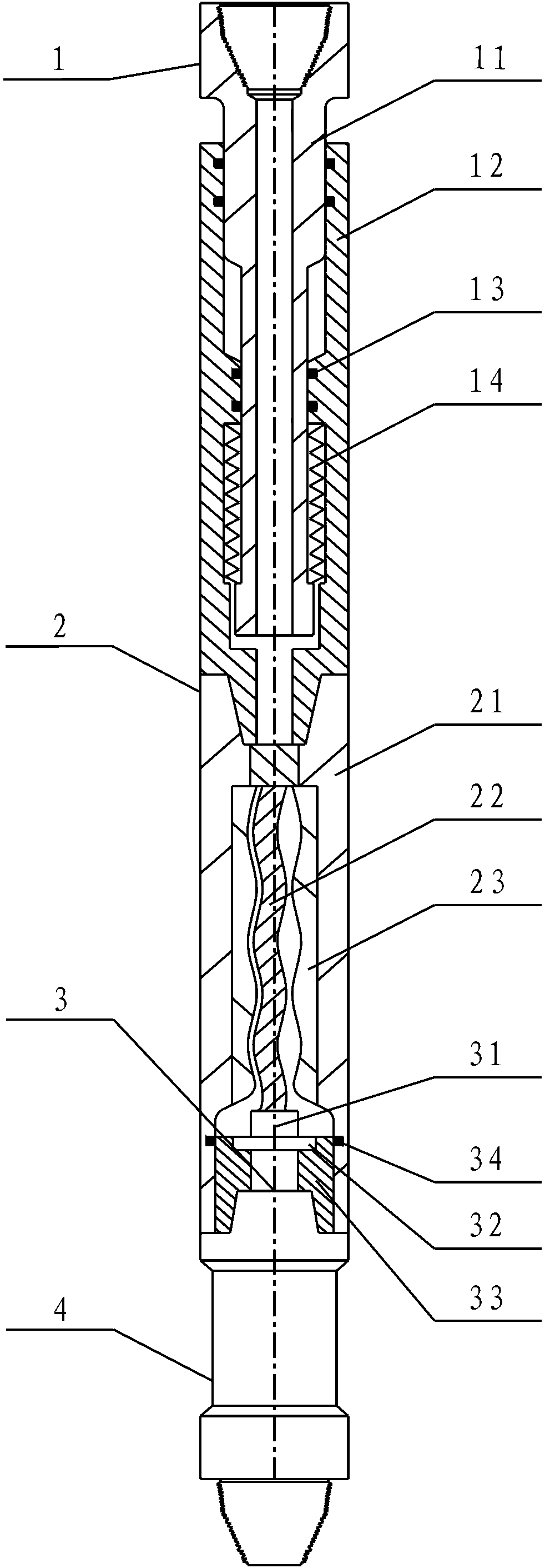
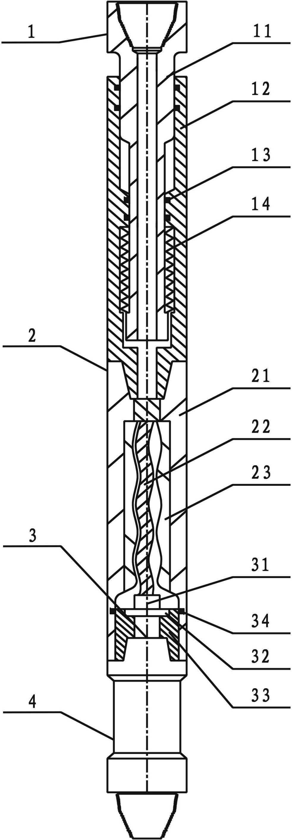
[0020] When the drilling hydraulic oscillator of the present invention is used to generate mechanical vibration, the vibration nipple 1 is connected with the hydraulic drive assembly 2, the rotor 22 is connected with the vibration valve 31, the fixed valve assembly 3 is installed on the bottom assembly 4, and the power casing The body 21 is connected to the bottom assembly 4 .

[0021] The vibrating short joint 1 mainly includes a vibrating shell 12, a disc spring 14, and a mandrel 11 with a flow channel processed in the center of the shaft. The mandrel 11 is loaded into the vibrating shell 12 and can slide up and down in the shell 12. The mandrel The space between the non-contact walls between 11 and the vibrating shell 12 is an annular space, the disc spring 14 is arranged in the annular space, and a seal is set between the wall contact surface of the...


PUM


Abstract

The invention relates to a hydro-oscillator for well drilling. The hydro-oscillator consists of a hydraulic driving assembly, a fixed valve assembly, a bottom assembly and a vibrating pipe nipple, wherein the vibrating pipe nipple is connected with the hydraulic driving assembly; a rotor is connected with a vibrating valve; the fixed valve assembly is arranged on the bottom assembly; and a power shell is connected with the bottom assembly. A drilling fluid is used for driving the rotor to rotate, and the rotor is used for driving the vibrating valve to vibrate, so that flow holes of the vibrating valve and a fixed valve are staggered with each other, and simple harmonic pressure waves are modulated and are upwardly transmitted to a disc spring for driving the vibrating shell to perform continuous simple harmonic vibration in the axial direction, so that the friction resistance between a drilling column and a well wall is improved effectively, and the drilling speed is increased; and meanwhile, pressure waves are downwardly transmitted to drill bit jet flow, so that periodic change of rock breaking pressure is facilitated, and rocks are crushed effectively. The hydro-oscillator has the characteristics of simple structure, convenience for operating, safety, reliability, low pressure drop, high adaptability, no influence on the drilling tool structure and the like, and plays an important role in increasing the drilling speed and reducing cost.

Description

technical field [0001] The invention relates to a hydraulic oscillator for drilling, in particular to a drilling speed-increasing device for reducing well wall frictional resistance and improving rock-breaking efficiency, which belongs to a supporting device for oil and natural gas drilling. Background technique [0002] During the drilling process, the method of rock breaking is an important factor affecting the drilling speed. Downhole obstruction or stuck drill will seriously affect the drilling process. As the current wellbore becomes more and more irregular, the extended-reach drilling mode faces greater challenges. Reducing friction, reducing sticking accidents in conventional drilling, increasing dynamic drilling pressure, and improving the efficiency of conventional drilling are problems that need to be solved urgently in current drilling projects. Field practice shows that applying appropriate periodic axial vibration to the drill string can effectively reduce the ...

Claims


Application Information

Patent Timeline
Patent Type & Authority Applications(China)
IPC IPC(8): E21B7/24E21B28/00
Inventor 涂辉信石玉陈涛车强
Owner CHINA PETROCHEMICAL CORP
Why Eureka
Try Eureka