Method for reducing drive eccentric errors of harmonic gear and automatic aligning wave generator

An automatic centering and wave generator technology, applied in the direction of gear transmission, transmission, belt/chain/gear, etc., can solve the problem of damage to gear teeth, eccentricity error between the geometric center of flexible spline and the center of rotation, and the inability to eliminate the tooth backlash and eccentricity errors to achieve the effect of eliminating tooth backlash and reducing eccentricity errors

Active Publication Date: 2012-10-03
深圳市东汇精密机电有限公司
View PDF6 Cites 6 Cited by
  • Summary
  • Abstract
  • Description
  • Claims
  • Application Information

AI Technical Summary

Problems solved by technology

[0004] Since the processing and assembly errors of each part of the harmonic gear transmission are unavoidable, the gear of the flex spline 91 and the gear of the rigid spline 92 have backlash and the geometric center of the flex spline and the rotation The eccentric error of the center seriously affects the transmission accuracy and dynamic performance of the harmonic gear transmission
Since the long-axis dimension of the wave generator 90' is fixed, it cannot eliminate the backlash and eccentricity errors caused by machining and assembly errors, and the gear teeth will be damaged when overloaded.
Therefore, if the harmonic gear transmission is to obtain high transmission accuracy, higher requirements must be placed on the machining accuracy of each part and the assembly accuracy of the transmission device, but a series of problems such as high cost and difficult process will arise.
At present, there is no wave generator that can eliminate the eccentricity error and tooth backlash of harmonic gear transmission at the same time, and can also protect against overload.

Method used


Image

  • Method for reducing drive eccentric errors of harmonic gear and automatic aligning wave generator
  • Method for reducing drive eccentric errors of harmonic gear and automatic aligning wave generator
  • Method for reducing drive eccentric errors of harmonic gear and automatic aligning wave generator

Examples


Embodiment Construction

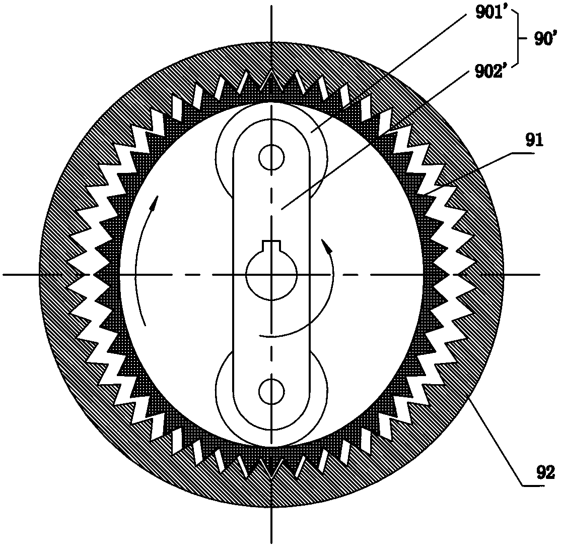
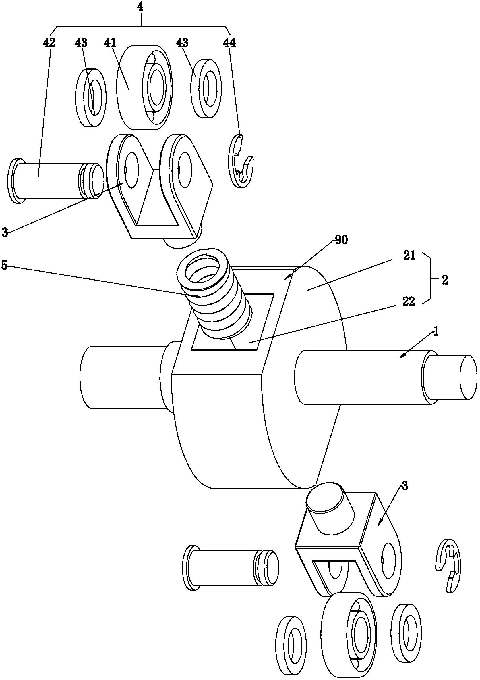
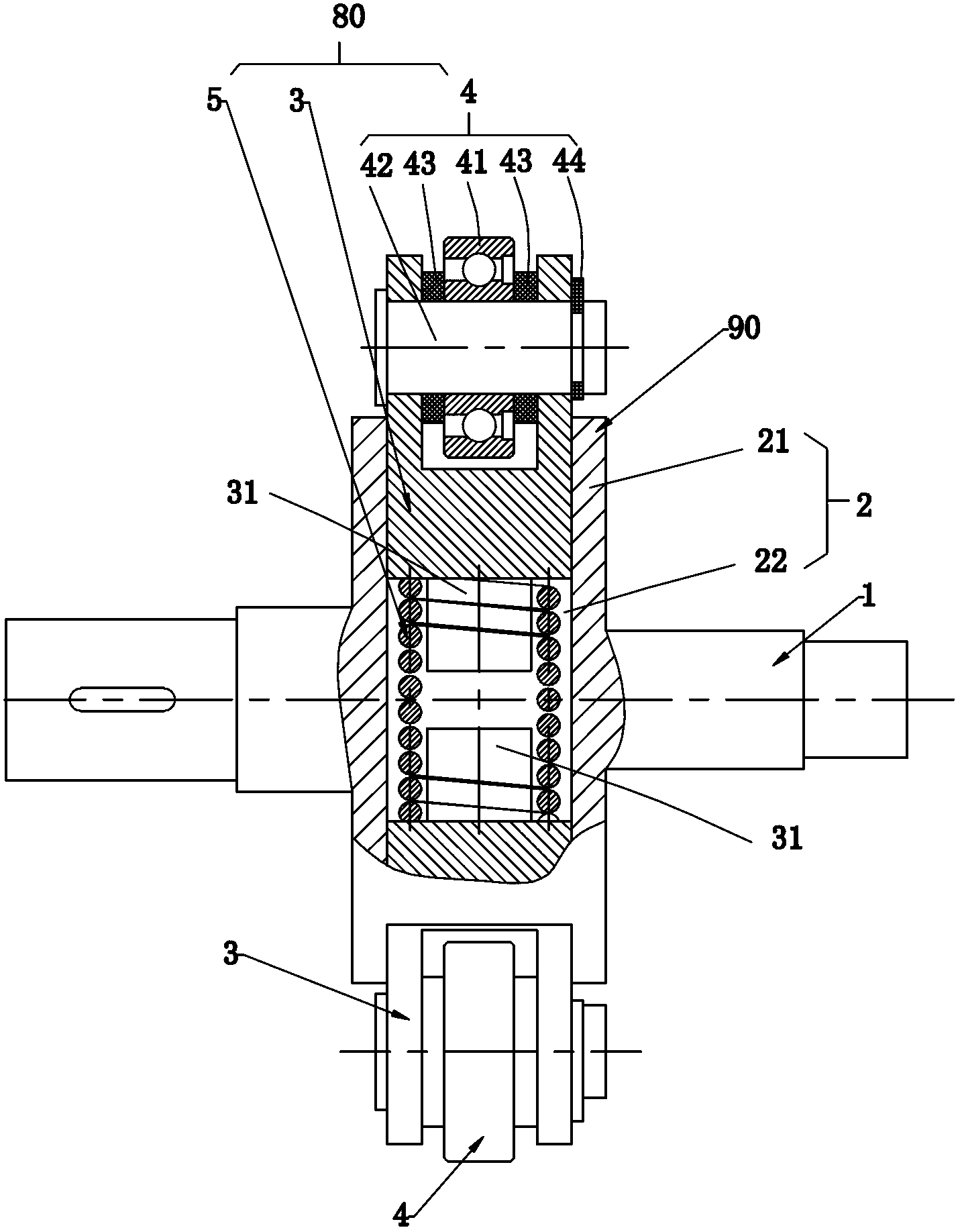
[0032] like Figure 2 to Figure 4 As shown, the embodiment of the present invention provides a self-aligning wave generator 90 for a harmonic gear transmission, including an input shaft 1 , a turntable 2 and an elastic floating mechanism 80 . The elastic floating mechanism 80 includes two roller brackets 3 , an elastic member 5 arranged between the two roller brackets 3 , and a roller assembly 4 including a roller 41 arranged on the roller brackets 3 .

[0033] The input shaft 1 is used to drive the turntable 2, and the middle of the turntable 2 is provided with a through hole for the elastic member 5 to slide therein.

[0034] The turntable 2 includes a body 21 and a slideway 22 . The turntable 2 is sheathed and fixed on the input shaft 1 by the body 21 and rotates with the input shaft 1. The slideway 22 is used for the elastic floating mechanism 80 to slide therein and guide its sliding, which is Extending along the long axis of the self-aligning wave generator 90 and pass...


PUM


Abstract

The embodiment of the invention discloses a method for reducing drive eccentric errors of a harmonic gear and an automatic aligning wave generator. The automatic aligning wave generator comprises a turn plate driven by an input shaft and an elastic floating mechanism provided with two rollers. The elastic floating mechanism is flexibly arranged inside the turn plate in a sliding manner in the long axis direction of the automatic aligning wave generator. The elastic floating mechanism comprises two roller brackets symmetrically distributed relatively to the centre of the turn plate and an elastic element arranged between the roller brackets; the elastic element elastically resists against the two roller brackets, and the two rollers are respectively arranged on the two roller brackets, elastically resist against an inner circle of a flexible gear under the action of the elastic element and force the flexible gear to form an ellipse from a round shape, so that gear teeth of the flexible gear are tightly meshed with gear teeth of a rigid gear. The automatic aligning wave generator can reduce the eccentric errors caused by processing and assembling of parts, can remove the gear backlash between the gear teeth of the flexible gear and the gear teeth of the rigid gear and play an overload protection role.

Description

technical field [0001] The invention relates to the field of mechanical transmission, in particular to an automatic centering wave generator and a method for using the automatic centering wave generator to reduce the eccentric error of harmonic gear transmission. Background technique [0002] Harmonic gear transmission technology is a new type of transmission technology produced with the development of aerospace technology in the late 1950s. It uses the controllable wave deformation produced by flexible components to realize the transmission of motion and power. Compared with the traditional transmission mechanism, it has many unique advantages such as high motion precision, small hysteresis, small size, high bearing capacity, high transmission accuracy and high transmission efficiency, and has been successfully applied in the fields of space technology, instrumentation, robots, printing machinery and medical equipment. middle. At present, in the harmonic drive, the most wi...

Claims


Application Information

Patent Timeline
Patent Type & Authority Applications(China)
IPC IPC(8): F16H1/32F16H1/48
Inventor 钟健马金平
Owner 深圳市东汇精密机电有限公司
Why Eureka
Try Eureka