Laminated magnetic bead with large high-frequency impedance

A high-frequency impedance and stacking technology, which is applied to piezoelectric/electrostrictive/magnetostrictive devices, electrical components, circuits, etc., can solve the problems of wasting manpower and material resources, reduce costs and increase high-frequency impedance , The effect of reducing the dielectric constant and loss

Inactive Publication Date: 2012-10-03
SHENZHEN SUNLORD ELECTRONICS
View PDF4 Cites 4 Cited by
  • Summary
  • Abstract
  • Description
  • Claims
  • Application Information

AI Technical Summary

Problems solved by technology

Moreover, when changing different materials in the actual manufacturing process, it is necessary to clean equipment such as the ball mill for preparing ferrite slurry, the ferrite slurry agitator and coating machine for making laminated magnetic bead blanks, which is necessary for production. Planning and production management brings many changes, but also wastes manpower and material resources

Method used


Image

  • Laminated magnetic bead with large high-frequency impedance
  • Laminated magnetic bead with large high-frequency impedance
  • Laminated magnetic bead with large high-frequency impedance

Examples


specific Embodiment approach 1

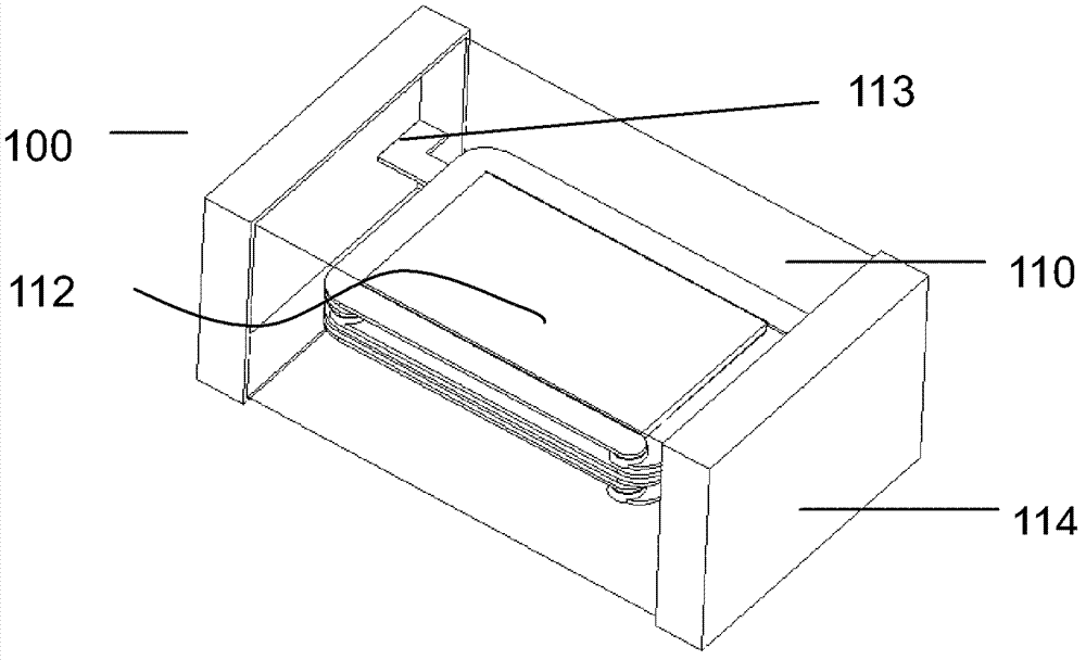
[0033] a kind of like Figure 1~4 The laminated magnetic bead 100 with large high-frequency impedance shown includes a laminated body 110 formed by laminating a conductor forming a coil, that is, an internal electrode 113 and an insulator, and an external terminal electrode 114. The external terminal electrode 114 is arranged on the laminated layer. The lengthwise direction of the body 110, that is, the two ends in the longitudinal direction, are respectively connected to the two ends of the coil.

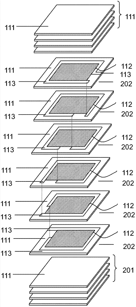
[0034] The laminated body 110 is a structure in which at least two types of insulator sheets are stacked together, one type is the first insulator sheet 201 of ferrite magnetic material constituting the upper and lower substrates of the laminated body 110, and the other is The type is the second type of insulator sheet 202 near the internal electrode 113 that constitutes the laminated body. Its main body is a plurality of first insulators 111 composed of ferrite magnetic materials ...

specific Embodiment approach 2

[0044] A large high-frequency impedance laminated magnetic bead 100, the structure of which is basically the same as that of Embodiment 1, the difference lies in:

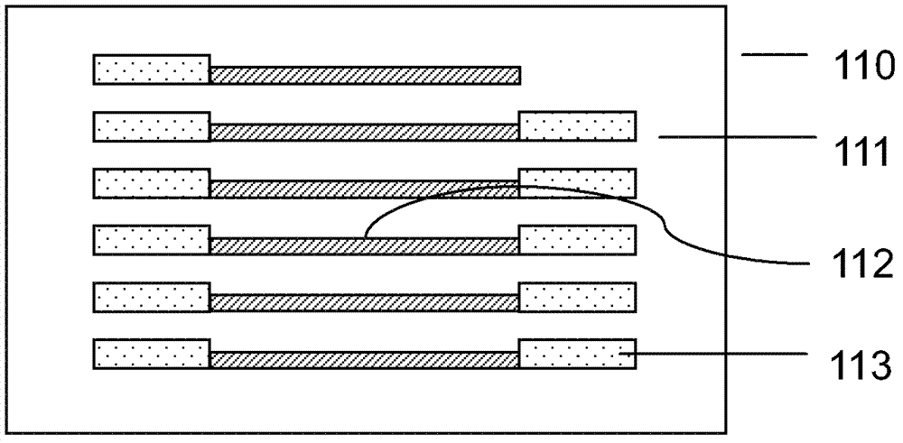
[0045] At least one layer of second insulator 112 is at a specific position inside the plurality of first insulators 111 such as Figure 5As shown, it is between two adjacent coil conductor layers and facing the coil conductors, that is, the second insulator 112 is between two layers of internal electrodes 113 and facing the internal electrodes 113 .

specific Embodiment approach 3

[0046] A large high-frequency impedance laminated magnetic bead 100, the structure of which is basically the same as that of Embodiment 2, the difference lies in:

[0047] At least one layer of second insulator 112 is at a specific position inside the plurality of first insulators 111 such as Image 6 As shown, it is the interlayer sandwiched by two adjacent coil conductors, that is, between two layers of internal electrodes 113 and the area does not exceed the position where the internal electrodes 113 are located, so as to reduce the linear expansion between the first insulator and the second insulator Problems caused by coefficient mismatch.


PUM


Abstract

The invention provides a laminated magnetic bead with large high-frequency impedance. A lamination body is in a structure formed by laminating at least two types of insulator thin sheets as a whole body; one type is a first insulator thin sheet which is made of a ferrimagnetism material and used for forming upper and lower substrates of the lamination body; and the other type is a second insulator thin sheet which is close to an internal electrode and is used for forming the lamination body; the main body of the lamination body is provided with a plurality of first insulators made of the ferrimagnetism material and at least one layer of a second insulator which is arranged at a specific position inside a first insulating layer and is made of a material with low dielectric constant and low consumption; and a coil conductor of a coil layer is arranged in each first insulator; and the dielectric constant and the consumption of the entire material of the laminated magnetic bead can be reduced by adjusting a layer quantity and the thickness of the second insulator, namely the stray capacitance is reduced, so that the high-frequency impedance of the laminated magnetic bead can be increased. Furthermore, a series of the laminated magnetic beads with the different high-frequency impedances can be obtained by only using one kind of ferrite slurry. Compared with the design of the traditional various ferrite materials, the cost can be greatly reduced.

Description

technical field [0001] The invention relates to magnetic beads, in particular to a laminated magnetic bead with large high-frequency impedance. Background technique [0002] The main parameters of laminated ferrite beads include impedance at a specific frequency suitable for the application. As the frequency of use of magnetic beads increases, the high-frequency impedance of the magnetic beads needs to be increased. In order to maximize the high-frequency impedance, it is necessary to reduce the stray capacitance in the laminated ferrite bead. However, the existing method to increase the high-frequency impedance is to change the formula of ferrite magnetic materials, usually it is necessary to prepare a variety of different ferrite magnetic materials, and even store a variety of ferrite slurries at the same time to meet different customers. needs. Moreover, when changing different materials in the actual manufacturing process, it is necessary to clean equipment such as th...

Claims


Application Information

Patent Timeline
Patent Type & Authority Applications(China)
IPC IPC(8): H01L41/047H01L41/083H01F27/28H10N30/87H10N30/50
Inventor 李有云陆达富刘先忺
Owner SHENZHEN SUNLORD ELECTRONICS
Why Eureka
Try Eureka