Numerical control stone multi-plate continuous cutting assembly line

An assembly line and stone technology, applied in the direction of stone processing tools, stone processing equipment, work accessories, etc., can solve the problems of high labor intensity, unsanitary and unsafe working environment, etc., to ensure the health and safety of the working environment, and prevent dust and water mist. The effect of spillover and high degree of automation

Active Publication Date: 2012-10-10
LAIZHOU FULIN MACHINERY
View PDF9 Cites 11 Cited by
  • Summary
  • Abstract
  • Description
  • Claims
  • Application Information

AI Technical Summary

Problems solved by technology

[0002] At present, most of the existing stone cutting machines are single saw blades, and a few are multi-blade cutting machines; but these stone cutting machines all need manual loading, picking up waste edges, and unloading, which is time-consuming and laborious. Low cutting efficiency, high labor intensity and high production cost
[0003] The cutting range and specifications of the multi-blade cutting machine are too single, and one motor in the spindle cutting mechanism can only drive 1 to 2 saw blades to work. A complete cutting task requires repeated operations to complete, which not only complicates the structure, but also increases the The number of motors is reduced, and the installation and operation are very troublesome
[0004] In addition, there is only a simple protective cover around the saw blade, and its protective effect is not very good for the more dust and serious dust pollution generated, which will make the operator's working environment unhygienic and unsafe

Method used


Image

  • Numerical control stone multi-plate continuous cutting assembly line
  • Numerical control stone multi-plate continuous cutting assembly line
  • Numerical control stone multi-plate continuous cutting assembly line

Examples


Embodiment Construction

[0046] The present invention will be described in further detail below in conjunction with the accompanying drawings and specific embodiments.

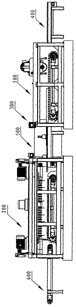
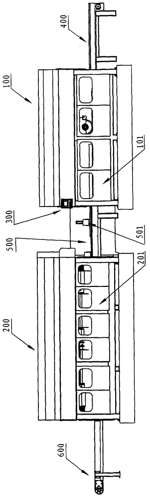
[0047] Such as figure 1 , figure 2 As shown, the overall structure of the present invention is composed of six major parts, including the numerical control system 300, and the feeding workbench 400, No. I longitudinal cutting machine 100, transition workbench 500, and No. II The horizontal cutting machine 200 and the blanking workbench 600 ; the working cooperation and connection between the above five components are automatically controlled by the numerical control system 300 . in:

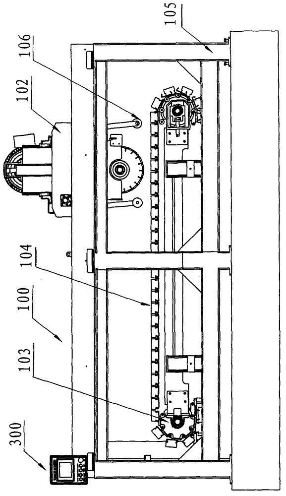
[0048] (1) No. I longitudinal cutting machine: refer to Figure 1-Figure 4 .

[0049] No. 1 longitudinal cutting machine 100 mainly realizes the longitudinal trimming of slate.

[0050] Depend on figure 2 It can be seen that No. I longitudinal cutting machine 100 is referred to as No. I machine for short, and it is installed on No. I frame 105 by...


PUM


Abstract

The invention discloses a numerical control stone multi-plate continuous cutting assembly line, which comprises a numerical control system, and a feeding workbench, a longitudinal cutter I, a transition workbench, a transverse cutter II and a discharging workbench which are arranged in movement direction of a stone plate in sequence, wherein the transverse cutter II comprises a transverse multi-blade saw set II, a machine workbench II, a hydraulic lifting system, a cross beam transverse reciprocating motion driving mechanism and a positioning device; machine saw blade shafts II in the II transverse multi-blade saw set are two saw blade shafts which are arranged along the same axis and are driven by a motor respectively; a connection structure is arranged between the inner ends of the two saw blade shafts; and the outer ends of the two saw blade shafts are provided with a locking structure respectively. According to the numerical control stone multi-plate continuous cutting assembly line, an entire piece of stone plate which meets the thickness requirement can be automatically and continuously cut into a plurality of rectangular plates of a required size, so that the numerical control stone multi-plate continuous cutting assembly line has the advantages of high automation degree, low labor intensity, high cutting efficiency, long service life, low production cost and the like.

Description

technical field [0001] The invention relates to a stone cutting machine, in particular to a numerical control stone multi-piece continuous cutting assembly line. Background technique [0002] At present, most of the existing stone cutting machines are single saw blades, and a few are multi-blade cutting machines; but these stone cutting machines all need manual loading, picking up waste edges, and unloading, which is time-consuming and laborious. The cutting efficiency is low, the labor intensity is high, and the production cost is high. [0003] The cutting range and specifications of the multi-blade cutting machine are too single, and one motor in the spindle cutting mechanism can only drive 1 to 2 saw blades to work. A complete cutting task requires repeated operations to complete, which not only complicates the structure, but also increases the The number of motors is reduced, and installation and operation are very troublesome. [0004] In addition, only a simple prot...

Claims


Application Information

Patent Timeline
Patent Type & Authority Applications(China)
IPC IPC(8): B28D1/04B28D7/00B28D7/02
Inventor 姜建斌贾树平程俊东
Owner LAIZHOU FULIN MACHINERY
Why Eureka
Try Eureka