Forced flow mixing technology and device for solar photo-thermal power generation energy storage tank body

A technology of photothermal power generation and solar energy, applied in the direction of solar thermal power generation, solar thermal devices, heating devices, etc., can solve the problems of temperature gradient difference, condensation at the bottom, solidification, unfavorable large-scale use, etc., to achieve improved stability and easy maintenance Effect

Inactive Publication Date: 2012-10-10
江苏太阳宝新能源有限公司
View PDF4 Cites 8 Cited by
  • Summary
  • Abstract
  • Description
  • Claims
  • Application Information

AI Technical Summary

Problems solved by technology

[0002] The solar thermal power generation energy storage system must have an energy storage medium for high-temperature heat storage. The energy storage medium is generally molten salt or other phase change materials. These heat storage mediums have high melting latent heat and high requirements for a specific temperature (melting point). For special reasons, the liquid surface temperature of the heat storage medium in the energy storage tank and the temperature at the bottom tend to form a temperature gradient difference, which makes the heat storage of the system uneven. In severe cases, condensation and solidification will occur at the bottom, which will affect the stability of the entire solar thermal power generation system.
[0003] The traditional solution is to use electric heat tracing around the tank wall for heating, and use natural convection to balance the temperature. However, due to the low efficiency and poor effect of natural convection, the above problems cannot be fundamentally solved. In addition, electric heat tracing uses And maintenance costs are high, life is low, not conducive to large-scale use

Method used


Image

  • Forced flow mixing technology and device for solar photo-thermal power generation energy storage tank body

Examples


Embodiment Construction

[0014] The present invention will now be described in further detail in conjunction with the accompanying drawings and preferred embodiments. These drawings are all simplified schematic diagrams, which only illustrate the basic structure of the present invention in a schematic manner, so they only show the configurations related to the present invention.

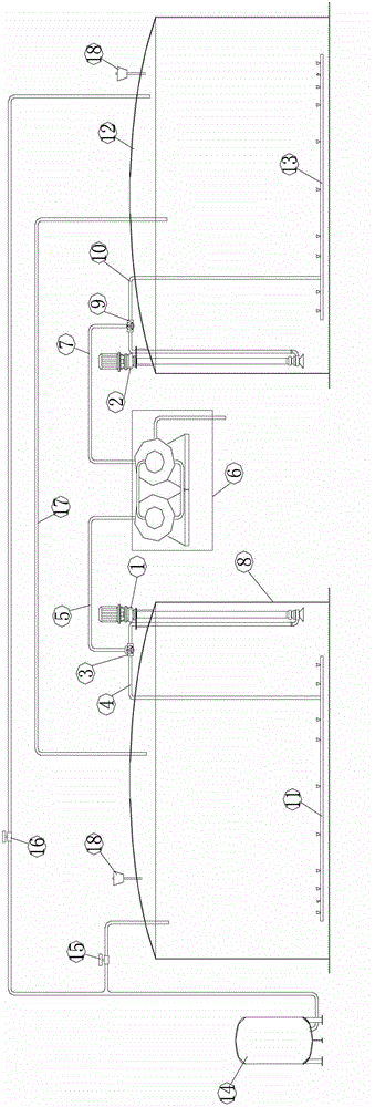
[0015] Such as figure 1 Shown is a double-tank energy storage mixed flow device, which has two energy storage tanks with the same structure, including: pump sets 1 and 2, automatic control three-way valves 3 and 9, pipelines 4, 5, 7 and 10, replacement Thermal (heating) system 6, energy storage tanks 8 and 12, mixed flow nozzles 11 and 13, inert gas protection system 14, automatic control valves 15 and 16, tank body pressure stabilization communication pipeline 17, breathing pressure regulating valve 18.

[0016] Energy storage tanks 8 and 12 are provided with a mixed-flow nozzle at the bottom of the tank body. The mixed-fl...


PUM


Abstract

The invention relates to a forced flow mixing technology for a solar photo-thermal power generation energy storage tank body. When the solar photo-thermal power generation energy storage tank body is filled with a heat storage medium, inert gas protection systems fill up inert protection gases into the energy storage tank at the same time, the energy storage medium exchanges heat or passes through a heating system and is filled into the energy storage tank body through a pipeline and an automatic control three-way valve on the pipeline, at the time, the energy storage medium forms a flow mixing vortex in the energy storage tank body through a flow mixing nozzle at the bottom of the energy storage tank body so as to perform uniform flow mixing on the energy storage medium in the energy storage tank body. The forced flow mixing technology is efficient, economic and easy to maintain, effectively solves the problems of temperature stratification and non-uniform heat storage temperature of the phase change energy storage medium in the solar photo-thermal power generation energy storage system, and greatly improves the running stability of the system.

Description

technical field [0001] The invention relates to the technical field of solar photothermal power generation energy storage, in particular to a technology of forced mixed flow in a solar photothermal power generation energy storage tank and a device thereof. Background technique [0002] The solar thermal power generation energy storage system must have an energy storage medium for high-temperature heat storage. The energy storage medium is generally molten salt or other phase change materials. These heat storage mediums have high melting latent heat and high requirements for a specific temperature (melting point). For special reasons, the liquid surface temperature of the heat storage medium in the energy storage tank and the temperature at the bottom tend to form a temperature gradient difference, which makes the heat storage of the system uneven. [0003] The traditional solution is to use electric heat tracing around the tank wall for heating, and use natural convection to...

Claims


Application Information

Patent Timeline
Patent Type & Authority Applications(China)
IPC IPC(8): F24J2/46
CPCY02E10/40
Inventor 张雷刘平心何毅刘国敏郭廷伟殷建平田洪增
Owner 江苏太阳宝新能源有限公司
Why Eureka
Try Eureka