Supercharge Your Innovation With Domain-Expert AI Agents!

Loop heat pipe structure

A loop heat pipe and tube body technology, which is applied to circuits, indirect heat exchangers, lighting and heating equipment, etc., can solve problems such as large space, difficulty in initial startup of flat-plate loop heat pipes, and thermal resistance of most parts of the evaporator. To achieve the effect of improving heat dissipation efficiency

Inactive Publication Date: 2012-10-10
BEIJING AVC TECH RES CENT
View PDF3 Cites 20 Cited by
  • Summary
  • Abstract
  • Description
  • Claims
  • Application Information

AI Technical Summary

Problems solved by technology

[0004] Although the loop heat pipe (Loop Heat Pipe LHP) has many advantages, because the traditional loop heat pipe uses a cylindrical structure evaporator, the evaporator of the loop heat pipe needs a large space, and because the outer surface of the cylinder is an arc surface , so it cannot be in direct contact with the heat source. In view of this, another flat-plate loop heat pipe is developed, and a single capillary structure is used as the wick structure, and a single capillary structure as the wick structure will make the heating evaporate The heat of the device can easily enter the supplementary chamber (resevior / compensation chamber), that is, serious heat leakage occurs. To prevent serious heat leakage, the capillary structure with low thermal conductivity must be used as the core (Wick) structure, then It will cause the evaporator to generate a large local thermal resistance, and if a single-layer capillary structure with high thermal conductivity is used as the core (Wick) structure, it will make the initial start-up of the flat-plate loop heat pipe quite difficult, that is, an excessively large Start critical power, even unable to start under some special working conditions
[0005] In addition, the shell material of the traditional flat-plate loop heat pipe is generally the same material as the bottom plate, while the bottom plate of the evaporator pursues high thermal conductivity. Furthermore, due to the particularity of the structure of the flat-plate loop heat pipe, when the bottom plate of the evaporator is heated, The problem of heating the working fluid inside the supplementary chamber (resevior / compensation chamber) through heat conduction on other walls except the bottom plate is very serious, and sometimes this part of the heat can even be equivalent to the heat leakage generated by the wick structure inside the evaporator , when the above two conditions are combined, the thermal performance of the flat-plate loop heat pipe becomes very poor, and the advantages of the flat-plate loop heat pipe cannot be fully utilized

Method used


Image

  • Loop heat pipe structure
  • Loop heat pipe structure
  • Loop heat pipe structure

Examples


Embodiment Construction

[0038] The above-mentioned objects and structural and functional characteristics of the present invention will be described based on the preferred embodiments of the accompanying drawings.

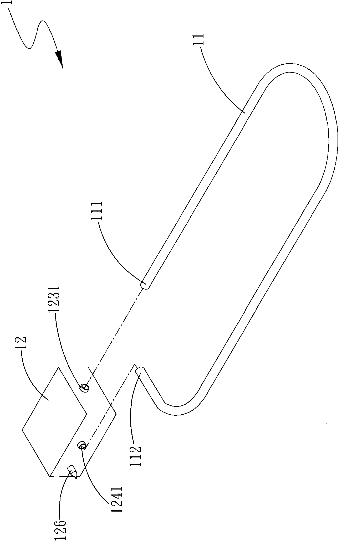
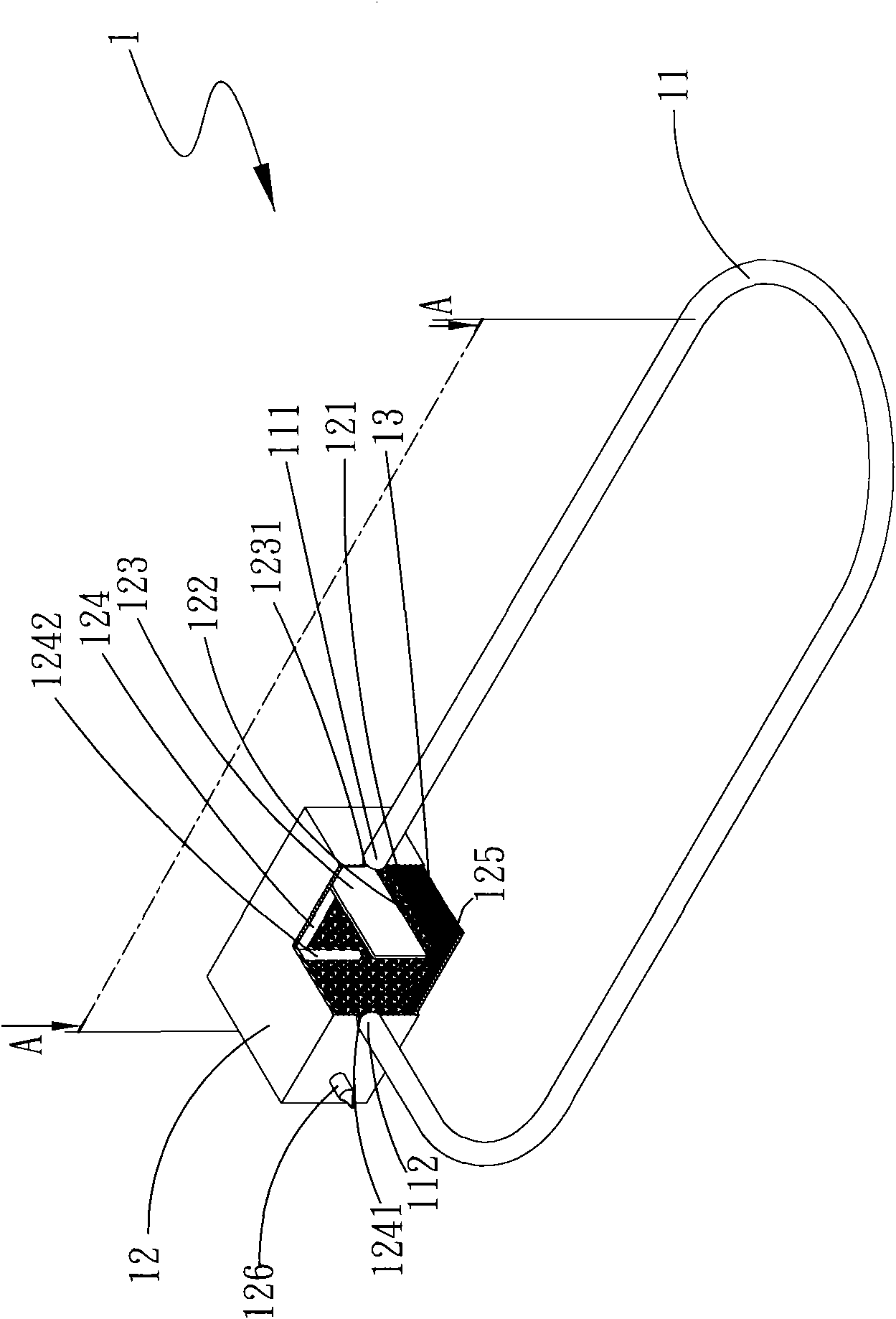
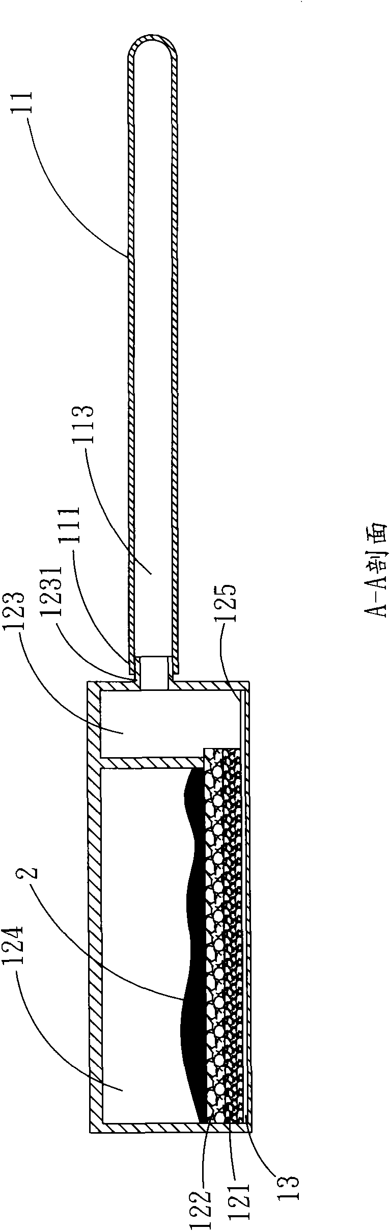
[0039] See figure 1 , figure 2 , image 3 , Is a three-dimensional exploded and combined cross-sectional view and AA cross-sectional view of the first embodiment of the loop heat pipe structure of the present invention. As shown in the figure, the loop heat pipe structure 1 of the present invention includes: a tube body 11, a cavity 12, and a first A capillary layer 121, a second capillary layer 122 and multiple grooves 13;

[0040] The tube body 11 has a first end 111 and a second end 112 and a passage 113 which communicates with the first and second ends 111 and 112.

[0041] The cavity 12 has a first cavity 123 and a second cavity 124, working fluid 2 and a bottom 125, the first cavity 123 has a first connection hole 1231, and the second cavity 124 There is a second connecting hole 1241, and...


PUM


Abstract

The invention provides a loop heat pipe structure, comprising a pipe body, a cavity, a first capillary layer, a second capillary layer and a multiple grooves. The pipe body is communicated with the cavity which is equipped with a first cavity, a second cavity, a working fluid and a bottom. The first capillary layer and the second capillary layer are laminatedly arranged on the bottom. The multiple grooves are selected to be arranged on either one of the first capillary layer and the bottom. Through the above first capillary layer and the second capillary layer, overly high vapour pressure in the cavity can be avoided, in order to enhance overall heat radiation efficiency of the loop heat pipe.

Description

Technical field [0001] The present invention relates to a loop heat pipe structure, in particular to multiple capillary structures with different thermal conductivity and permeability arranged in a cavity, so as to avoid excessive vapor pressure in the cavity and improve the overall heat dissipation efficiency of the loop heat pipe The loop heat pipe structure. Background technique [0002] With the advancement of semiconductor technology, integrated circuits (ICs) have been widely used in the chips of electronic devices such as personal computers, notebook computers, and network servers. However, as the processing speed and functions of the integrated circuit are significantly improved, the waste heat generated by the integrated circuit is also significantly increased. If this waste heat cannot be effectively removed, the electronic device is likely to fail. Therefore, various heat dissipation methods have been proposed to quickly remove the waste heat generated by the integrat...

Claims


Application Information

Patent Timeline
Patent Type & Authority Applications(China)
IPC IPC(8): H01L23/427H01L23/473F28D15/04H05K7/20
CPCF28D15/0275F28D15/046F28D15/0266H01L23/427H05K7/20336H01L2924/0002H01L2924/00
Inventor 向军周小祥江贵凤
Owner BEIJING AVC TECH RES CENT
Features
  • R&D
  • Intellectual Property
  • Life Sciences
  • Materials
  • Tech Scout
  • Unparalleled Data Quality
  • Higher Quality Content
  • 60% Fewer Hallucinations
Learn More