High-efficiency low-cost push-pull type direct current transformer

A low-cost, push-pull technology, applied in the direction of converting DC power input to DC power output, instruments, and adjusting electrical variables, can solve the problems of balancing performance and cost, achieve simple and stable work, suppress peak voltage, prevent The effect of overcurrent problems

Inactive Publication Date: 2012-10-10
苏州爱能普电气有限公司
View PDF6 Cites 2 Cited by
  • Summary
  • Abstract
  • Description
  • Claims
  • Application Information

AI Technical Summary

Problems solved by technology

In response to the above problems, many solutions have been proposed, such as resistor-capacitor snubber circuits, active snubber circuits, etc., but there is still no good solution that can achieve a balance between performance and cost.

Method used


Image

  • High-efficiency low-cost push-pull type direct current transformer
  • High-efficiency low-cost push-pull type direct current transformer
  • High-efficiency low-cost push-pull type direct current transformer

Examples


Embodiment

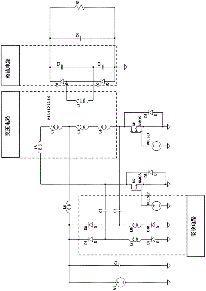
[0020] Example: such as figure 1 The high-efficiency and low-cost push-pull DC converter shown includes a push-pull circuit, a transformer circuit, an absorption circuit, and a rectifier circuit. The push-pull circuit includes two push-pull connected switch tubes and two switches connected in parallel Diode; the switching tube in this embodiment is a MOSFET tube, and the MOSFET tube M1, MOSFET tube M2, diode D5, and diode D6 form a push-pull circuit. The push-pull circuit is connected to the rectifier circuit through the transformer circuit. The absorbing circuit includes a first inductor L7, a second inductor L8, a first capacitor C7 and a second capacitor C8. The first inductor L7 and the first capacitor C7 form a series circuit and are connected with the transformer One end of the primary winding of the transformer circuit is connected; the second inductance L8 and the second capacitor C8 form a series circuit and are connected to the other end of the primary winding of ...


PUM


Abstract

The invention discloses a high-efficiency low-cost push-pull type direct current transformer. The direct current transformer comprises a push-pull circuit, a transformer circuit and a rectifier circuit, wherein the push-pull circuit comprises two switch tubes connected in a push-pull way and two diodes connected in parallel with the switch tubes, and is connected with the rectifier circuit through the transformer circuit. The direct current transformer is characterized by further comprising an absorption circuit, wherein the absorption circuit comprises a first inductor L7, a second inductor L8, a first capacitor C7 and a second capacitor C8; the first inductor L7 and the first capacitor C7 form a series circuit and are connected with one end of a primary winding of the transformer circuit; and the second inductor L8 and the second capacitor C8 form another series circuit and are connected with the other end of the primary winding of the transformer circuit. According to the direct current transformer, the peak voltage of the switch tube can be suppressed, the voltage withstanding requirement of the switch tube can be lowered, and the service life of a switching device can be prolonged; moreover, the switching loss can be reduced and the total efficiency of a power supply is improved.

Description

technical field [0001] The invention relates to a DC converter, in particular to a high-efficiency and low-cost push-pull DC converter. Background technique [0002] In many civil or industrial equipment, it is often required to convert one kind of direct current into another voltage of direct current, which requires the use of a direct current to direct current converter, referred to as a DCDC power supply. Common DCDC power supplies on the market are generally realized by a flyback circuit (with UC3845 or UC3843 as the driver chip); or by a push-pull circuit (with SG3525 as the driver chip). The push-pull DC converter is a commonly used power supply architecture, which has a simple structure and low cost. But it has some limitations, such as the switch tube used for push-pull has to withstand a large voltage, which is more than twice that of the power supply. Because there is leakage inductance in the primary winding of the transformer, when the switch tube is turned on ...

Claims


Application Information

Patent Timeline
Patent Type & Authority Applications(China)
IPC IPC(8): H02M3/337
Inventor 胡军胡小波
Owner 苏州爱能普电气有限公司
Why Eureka
Try Eureka