Dust collection device

A technology of dust removal device and blowing device, which is applied in the separation of dispersed particles, chemical instruments and methods, and filtration of dispersed particles, etc. Easy to install in place, prevent disconnection, and save the cost of use

Inactive Publication Date: 2012-10-17
解波
View PDF4 Cites 5 Cited by
  • Summary
  • Abstract
  • Description
  • Claims
  • Application Information

AI Technical Summary

Problems solved by technology

Since the diameter of the filter bag is larger than the diameter of the bag cage, the filter bag is tightly attached to the bag cage during filtration, and the filter bag is away from the bag cage during back blowing, so that the frequent contact and loosening of the filter bag and the bag cage will easily cause the filter bag and the bag cage to be separated. The parts where the vertical ribs contact are damaged by friction, which affects the service life of the filter bag, increases production costs, and affects safe production
In addition, the thickness of the bag cage is generally fixed. If the filter bag is enlarged due to the efficiency of the dust collector, the traditional bag cage is not adaptable, and it is easy to be trampled due to the filter bag being too large, resulting in an increase in cost.

Method used


Image

  • Dust collection device
  • Dust collection device
  • Dust collection device

Examples


Embodiment 1

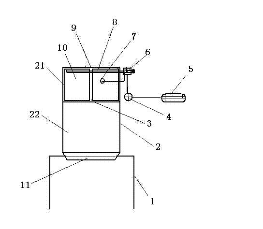
[0028] like figure 1 As shown, a dust removal device includes a support 1, the support 1 is located directly above the dust removal point, a box 2 is fixed on the support 1, the upper box 21 of the box 2 and the lower box 22 is provided with a deflector 3 in the middle, and two bag-type dust collectors 10 are arranged inside the upper box body 21, and the bottom end of the lower box body 22 is movably connected with an ash unloading plate 11; the outer side of the box body is fixed There is a blowing device, and the blowing device communicates with the upper box body 21 through the blowing pipe 8 . The blowing device includes an air bag 4, the two ends of the air bag 4 are respectively connected to a centrifugal fan 5 and an electromagnetic pulse valve 6, and the electromagnetic pulse valve 6 is connected to the blowing pipe 8 located at the upper end of the upper box body 21; The filter bag 10 is provided with a controller 7 for detecting airflow resistance in the filter bag...

Embodiment 2

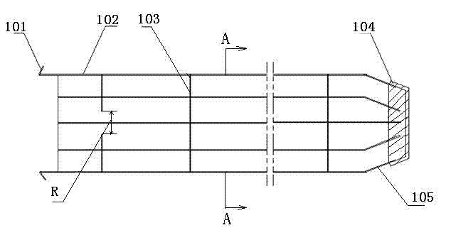
[0034] like figure 2 As shown, the bag cage of the dust collector includes a cage body composed of a top cover 104, vertical ribs 102, and ring ribs 103. The ring ribs 103 are arc-shaped and fixed to the vertical ribs 102, and the radius of the top cover 104 Smaller than the radius of the ring rib 103 , the vertical rib 102 is connected to the top cover 104 through the oblique rib 105 . The loop rib is made of elastic material PVC, the distance R between the two ends of the arc-shaped loop rib is 4CM, and the bottom end of the vertical rib 102 is provided with an upper bag hook 101 .

[0035] The gaps on the multiple ring ribs on the bag cage can be arranged on the vertical ribs in a staggered manner, so that the diameter of the bag cage can change more, which is more convenient for installation and protects the safety of the filter bag.

[0036] The bag cage of the bag type dust collector in the dust removal device of the present invention reaches the variable diameter of the...

Embodiment 3

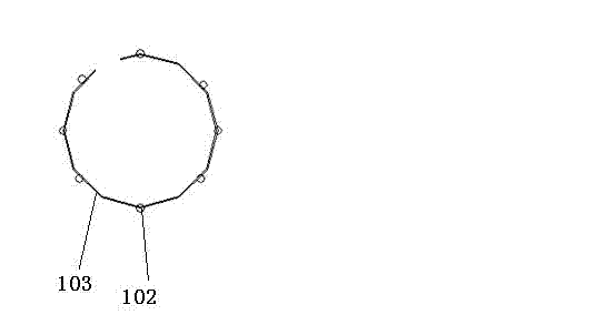
[0039] image 3 It is the A-A sectional view of the bag cage in the bag filter. The bag cage includes a cage body composed of a top cover, vertical ribs 102, and ring ribs 103. The ring ribs 103 are arc-shaped and fixed to the vertical ribs 2. The top cover The radius of the vertical rib 102 is smaller than the radius of the ring rib 103, and the vertical rib 102 is connected with the top cover through the oblique rib. Described loop rib is made of elastic material plastic, and the distance between the two ends of loop rib is 5CM, and the bottom end of vertical rib 102 is provided with upper bag hook.


PUM


Abstract

The invention provides a dust collection device, which comprises a bracket. The bracket is arranged right above a dust collection point, a box body is fixedly arranged on the bracket, and a deflector is arranged between the upper box body and the lower box body of the box body. A bag-type dust collector is arranged in the upper box body. The bottom end of the lower box body is movably connected with a dust discharging slide. A blowing device is fixedly arranged outside the box body. The blowing device is communicated with the upper box body through a blow tube. With the adoption of the dust collection device, the generated dust is absorbed to achieve the purpose of purifying the environment and realizing the standard of the environment protection. The detained dust on a filtering bag is timely cleared through pulse airflow, and therefore, the dust collection effect of the bag-type dust collector can be guaranteed.

Description

[0001] technical field [0002] The invention relates to a dust removal device, in particular to a bag type dust remover and a bag cage thereof. [0003] Background technique [0004] Production and processing enterprises all have exhaust gas treatment problems, especially in cement production enterprises, where dust pollution is particularly serious. There are a large number of small particles of dust flying everywhere when unloading in cement production tunnels and belt conveyors at the bottom of the warehouse. There are uneven unloading points and transfer points in the similar tunnels and the bottom of the reservoir, and there are at most twenty or so. These unloading points are all arranged in horizontal pipes due to space constraints. Long-distance horizontal pipes can easily cause pipe blockage. Each The dust spots are not evenly distributed, so the dust removal effect of general dust collectors is not ideal, and it is difficult to meet the emission standards. In ad...

Claims


Application Information

Patent Timeline
Patent Type & Authority Applications(China)
IPC IPC(8): B01D46/02B01D46/06
Inventor 解波
Owner 解波
Why Eureka
Try Eureka