
High-frequency centrifugal reverse molding machine

A technology of reverse molding and rotating motors, which is applied to centrifuges and other directions, and can solve problems such as expensive components and bulky machines

Active Publication Date: 2012-10-17
武汉金凰珠宝股份有限公司
View PDF3 Cites 4 Cited by
  • Summary
  • Abstract
  • Description
  • Claims
  • Application Information

AI Technical Summary

Problems solved by technology

[0003] The present invention discloses a centrifugal casting machine according to the defects of the centrifugal casting machine in the prior art, which includes a special and reasonable oscillation frame structure , its volume can be minimized as much as possible, and the energy consumption of vibration can also be reduced to the minimum. This vibration frame solves the two problems of bulky machine and expensive components in the prior art. Therefore, the centrifugal molding machine of the present invention Can be widely used in various industries such as jewelry, watches, plastics, leather and dental hospitals

Method used

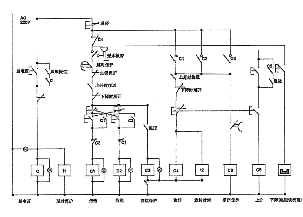

Image

  • High-frequency centrifugal reverse molding machine
  • High-frequency centrifugal reverse molding machine

Examples


Embodiment Construction

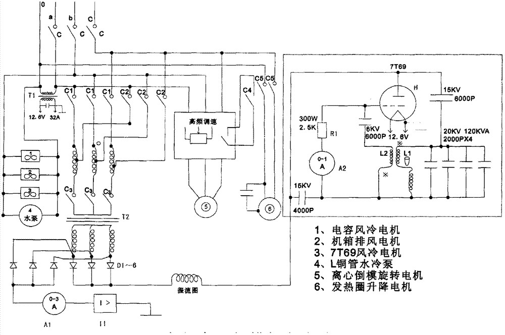
[0014] figure 1 The main circuit diagram of the centrifugal pouring machine of the present invention is shown, as figure 1 as shown,

[0015] The main circuit includes main power contactor C, transformer T1 and 7T69 electron tube, main power contactor C and T1 provide 12.6V filament voltage for transformer to 7T69 electron tube.

[0016] The main circuit also includes a transformer T2, rectifier diodes D1, D2, D3, D4, D5, D6 and rectifier coils, the transformer T2 is connected to the rectifier diodes D1, D2, D3, D4, D5 and D6 respectively and then connected to the rectifier coil, the above Transformer T2, rectifier diodes D1, D2, D3, D4, D5, D6 and rectifier coil constitute a three-phase full-wave rectifier circuit.

[0017] The main circuit also includes three low thermal contactors C1, three high thermal contactors C2, three rectification circuit main contactors C3, full wave rectification circuit output ammeter A1 and overcurrent protection relay I1, three low thermal con...


PUM


Abstract

The invention discloses a centrifugal reverse molding machine which is provided with a main circuit. The main circuit comprises a main power supply contactor C, a transformer T1, a 7T69 electron tube, a transformer T2, rectifier diodes D1, D2, D3, D4, D5 and D6, a rectifying coil, three low-heat contactors C1, three high-heat contactors C2, three rectifying circuit main contactors C3, a full-wave rectification circuit output ampere meter A1, an overcurrent protection relay I1, a capacitor filtering circuit and a high-frequency oscillating circuit. The high-frequency oscillating circuit comprises a cross-linking capacitor C1, a switch oscillating circuit, a grid ampere meter A2 and a grid bias voltage resistor R1, wherein the switch oscillating circuit comprises an electron tube H, an inductor L1, a capacitor C3 and an inductor L2. The centrifugal reverse molding machine is small in volume and low in cost.

Description

technical field [0001] This application relates to a molding machine. Background technique [0002] A centrifuge is a machine that uses centrifugal force to separate components in a mixture of liquid and solid particles or liquid and liquid. It is mainly used to separate the solid particles in the suspension from the liquid; or to separate two different densities and immiscible liquids in the emulsion. Special ultra-speed tube separators can also separate gas mixtures of different densities; using the characteristics of different sedimentation speeds of solid particles of different densities or particle sizes in liquids, some decanter centrifuges can also classify solid particles according to density or particle size. Centrifuges have been widely used in chemical industry, petroleum, food, pharmaceutical, mineral processing, coal, water treatment and shipbuilding and other departments. The centrifugal pouring machine combined with the principle of centrifugal pouring has b...

Claims


Application Information

Patent Timeline
Patent Type & Authority Applications(China)
IPC IPC(8): B04B13/00
Inventor 赵彬吴德金赵二亮史刚光俊洪皓
Owner 武汉金凰珠宝股份有限公司
Learn More