
Horizontal moving device for capillary pipe and pilger mill set having same device

A technology of traverse device and capillary tube, which is applied in metal rolling, manufacturing tools, metal rolling, etc., can solve the problems affecting the quality and output of steel pipe rolling, increasing energy consumption and gas emission, and long pick-up and delivery journeys, etc. Achieve the effects of shortening reheating time, reducing energy consumption and gas emissions, and improving rolling quality and output

Active Publication Date: 2014-08-06
TAIYUAN HEAVY IND
View PDF8 Cites 0 Cited by
  • Summary
  • Abstract
  • Description
  • Claims
  • Application Information

AI Technical Summary

Problems solved by technology

Since there are many front stations in the Pilger mill, including capillary incoming station, mandrel incoming station, capillary pre-heading station, three mandrel cooling stations and one rolling station, the traditional material feeding is adopted. The system requires repeated layout of the feeding and receiving system for multiple times, which will result in a large floor area and a long feeding journey, resulting in longer feeding time and large temperature drop of high-temperature capillary tubes, which will eventually affect the rolling quality and output of steel pipes
Moreover, after rolling out the blank pipe, due to the large temperature drop, the reheating time before being sent to the sizing process will be longer, which increases energy consumption and gas emissions

Method used


Image

  • Horizontal moving device for capillary pipe and pilger mill set having same device
  • Horizontal moving device for capillary pipe and pilger mill set having same device
  • Horizontal moving device for capillary pipe and pilger mill set having same device

Examples


Embodiment Construction

[0020] Specific embodiments of the present invention will be described in detail below in conjunction with the accompanying drawings. It should be understood that the specific embodiments described here are only used to illustrate and explain the present invention, and are not intended to limit the present invention.

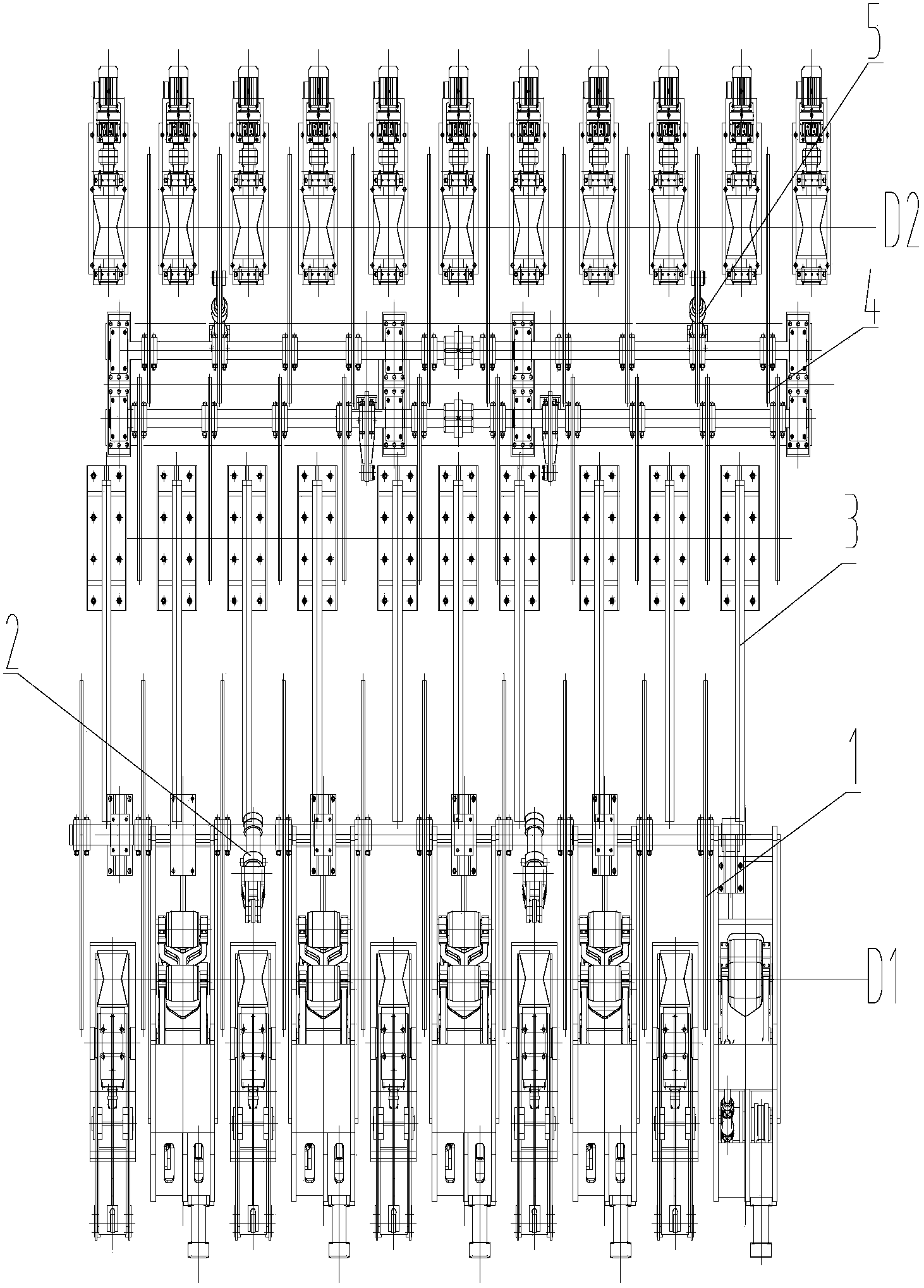
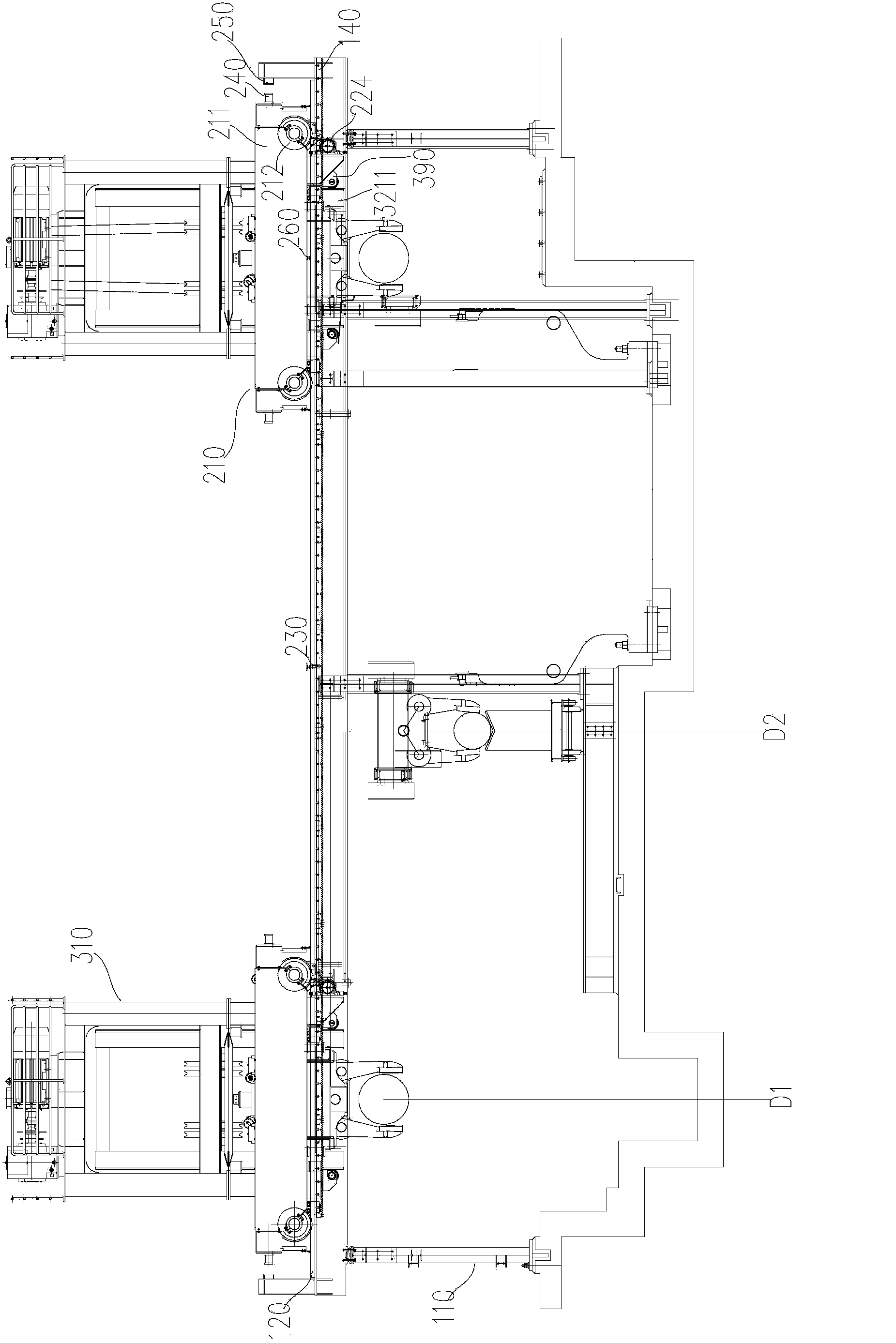
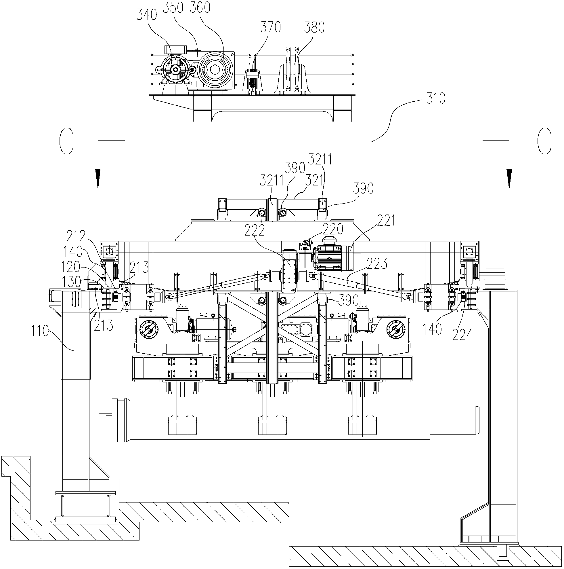
[0021] like figure 2 , 3 As shown, the capillary traversing device mainly includes a support beam frame, a traveling mechanism and a capillary lifting mechanism. The supporting beam frame includes a foot 110 fixed on the ground, a track 120 and a support frame 130 connecting the track 120 to the foot 110 . The rails 120 are arranged along both sides in the length direction of the working platform. A supporting frame 130 is provided between the supporting frame 110 and the track 120 . The supporting frame 130 is screwed to the supporting leg 110 . The lower surface of each support frame 130 is also provided with a rack 140 along the length direction of the w...


PUM


Abstract

The invention relates to a horizontal moving device for a capillary pipe and a pilger mill set having the same device. The horizontal moving device for the capillary pipe comprises a supporting beam frame, a travelling mechanism and a capillary pipe lifting mechanism, wherein the supporting beam frame comprises two rails and a plurality of support pins fixed on the ground; the travelling mechanism comprises a trolley and a driving component; the trolley is driven to move on the rails by the driving component; the capillary pipe lifting mechanism comprises a winding platform and a clamp component; the winding platform is located on the trolley; the winding platform is connected with the clamp component through a wire rope and a wire rope drum; and the clamp component is ascended or descended by winding or releasing the wire rope on the winding platform, so as to drive the capillary pipe clamped in the clamp component to ascend or descend. By using the horizontal moving device for the capillary pipe, material-stirring and material-receiving systems during a transferring process of a large number of high-temperature capillary pipes are saved, the connection of equipment on each station in front of a pilger mill is tighter and the structure is more compact, so that the material-conveying time is saved, the temperature drop of the high-temperature capillary pipe during the long-time transferring process is reduced and the rolling quality and yield of the steel pipe are increased.

Description

technical field [0001] The invention relates to the rolling of tubes, in particular to a capillary traverse device before a Pilger rolling mill, and a Pilger rolling mill unit with the device. Background technique [0002] The traditional capillary lateral movement is accomplished through the feeding and receiving system. The system moves the capillary from one station to another. After the transition device, it is transported to another station by the feeding mechanism of another station. [0003] E.g figure 1 The schematic diagram of the existing material shifting and receiving system shown is as follows, the specific implementation is as follows, the transfer of the incoming material from the Pilger mill to the station D2 from the station D1 is realized in this way, and the material shifting cylinder 2 drives the shifting rod 1 Transfer the incoming material to the transition stand 3, the transition stand 3 has a certain slope, the incoming material rolls to the end of ...

Claims


Application Information

Patent Timeline
Patent Type & Authority Patents(China)
IPC IPC(8): B21B39/02
Inventor 熊令芳
Owner TAIYUAN HEAVY IND
Learn More