A riveting assembly of a sensor protective cover

A sensor and protective cover technology, applied in the field of riveting and pressing assembly of sensor protective cover, can solve the problems of low work efficiency, low assembly efficiency, low work efficiency, etc., and achieve the effects of low cost, high production efficiency and reliable performance

Active Publication Date: 2014-10-15
宁波拓普电器有限公司
View PDF6 Cites 0 Cited by
  • Summary
  • Abstract
  • Description
  • Claims
  • Application Information

AI Technical Summary

Problems solved by technology

However, the protective cover on the general sensor, or through manual tooling, the work efficiency is low; or the sealing performance is not good, rainwater is easy to penetrate into it, which affects the practicability of the sensor
And the general sensor protective cover of prior art also does not effectively solve this problem at present
For example, Chinese Patent Publication No. CN 1744233 A, published on March 08, 2006, the name of the invention is Humidity Sensor Protective Cover, which discloses a sensor protective cover. Under extremely humid conditions, it effectively solves the problem of the measurement accuracy of the humidity sensor in a very short response time, but the surrounding wall and the front wall of this patent need to be installed separately, the assembly efficiency is low, and the front wall is sleeved on the probe of the sensor. On the needle, the overall sealing of the sensor is not good
Another example is the Chinese patent authorization announcement number CN 201007705 Y, announced on January 16, 2008. The name of the invention is an optical gas sensor protective cover. The application discloses a sensor protective cover. And the innovation of the left and right chambers and their structures, the sensor can work effectively for a long time under the conditions of high humidity and high dust, which solves the problem of the influence and harm of the sensor in the harsh environment, but the protective cover of the application and the sensor The shell is fixed by threaded connection, which is inconvenient to process, and under the condition of high concentration of dust, the dust is easy to crowd the threaded opening, which is not conducive to maintenance and loading and unloading of the protective cover, and does not play the role of threaded connection
Another example is the Chinese patent authorization announcement number CN 201170732 Y, the date of the authorization announcement was December 24, 2008. The name of the invention is a ventilation shield for air parameter sensors or recorders. This application discloses a sensor shield, through which , The innovation of the fan and its structure effectively solves the problem that the parameters detected by the sensor are consistent with the composition of the air around the sensor, but the protective cover and the sensor in this application are installed through the installation rod and the fixed bracket, the work efficiency is low, and there is no Solve the problem that the protective cover is easy to install

Method used


Image

  • A riveting assembly of a sensor protective cover
  • A riveting assembly of a sensor protective cover
  • A riveting assembly of a sensor protective cover

Examples


Embodiment 1

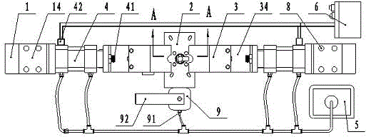
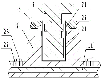
[0027] Embodiment one: combined with attached figure 1 , 2 , 3, a riveting assembly of a sensor protective cover, including a base plate 1, a fixed seat 2, two Huff molds 3, two cylinders 4, an air source 5 and a PLC electric control cabinet 6, a cylinder 4, and a fixed seat 2 It is fixedly connected with the bottom plate 1, the piston rod 41 of the cylinder 4 is fixedly connected with the half mold 3, the half mold 3 matches the sensor frame 7, the fixing seat 2 is provided with a positioning hole 21 matching the sensor protective cover 71, and the air source 5 is connected with the cylinder 4, and the PLC electric control cabinet 6 is connected with the electromagnetic valve 42 of the cylinder 4.

[0028]When installing, first fix the fixing seat on the bottom plate, then fix the two cylinders with the bottom plate according to the position of the fixing seat, then fix the two Huff molds to the piston rod on the cylinder respectively, and finally connect the cylinder Air ...

Embodiment 2

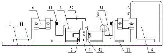
[0029] Embodiment two, combined with figure 1 , 2 , 3, 4, 5, a riveting assembly of a sensor protective cover, including a base plate 1, a guide rail 11 on the base plate 1, a fixing seat 2, a bracket 14, a connecting piece 34, two Huff molds 3, and two cylinders 4. Air source 5 and PLC electric control cabinet 6, fixed seat 2 and guide rail 11 are fixedly connected, cylinder 4 is connected with bottom plate 1 through bracket 14, bracket 14 is fixed with bottom plate 1 and cylinder 4 through hexagon socket bolt 8 respectively, and the connecting piece 34 is plugged with the guide rail 11, the cylinder 4 is connected with the half mold 3 through the connecting piece 34, the connecting piece 34 is threadedly connected with the piston rod 41 of the cylinder 4, and is fixedly connected with the half mold 3 through the inner hexagon bolt 8, and the half mold 3 Matching with the sensor frame 7, the fixed seat 2 is provided with a positioning hole 21 matching with the sensor protec...

Embodiment 3

[0031] Embodiment three, combined with the attached figure 1 , 2 , 3, 4, 5, 6, 7, a riveting assembly of a sensor protective cover, including a base plate 1, a guide rail 11 on the base plate 1, a fixing seat 2, a bracket 14, a connecting piece 34, and two Huff molds 3 , two cylinders 4, the rotary cylinder 9 on the fixed seat 2, the air source 5 and the PLC electric control cabinet 6, the fixed seat 2 is fixedly connected with the guide rail 11, the cylinder 4 is connected with the base plate 1 through the bracket 14, and the bracket 14 is connected with the base plate 1, Cylinders 4 are respectively fixed by hexagon socket bolts 8, connectors 34 are plugged into guide rails 11, cylinders 4 and Hough mold 3 are connected through connectors 34, connectors 34 are threaded with piston rod 41 of cylinder 4, and Huff mold 3 There are two hexagon socket bolt holes 81 matching the connecting piece 34 on the top, and one hexagon socket bolt hole 81 matching the connecting piece 34 ...


PUM


Abstract

The invention discloses a riveting assembly of a sensor protective cover, including a bottom plate (1), a fixing seat (2), two Huff molds (3), two cylinders (4), an air source (5) and a PLC Electric control cabinet (6), characterized in that the cylinder (4), the fixing seat (2) and the base plate (1) are fixedly connected, and the piston rod (41) of the cylinder (4) is connected to the Huff mold (3) fixedly connected, the Huff mold (3) is matched with the sensor skeleton (7), the fixed seat (2) is provided with a positioning hole (21) matched with the sensor shield (71), the air source ( 5) It is connected with the cylinder (4), and the PLC electric control cabinet (6) is connected with the solenoid valve (42) of the cylinder (4). Through the innovation of riveting tooling equipment and its structure, the present invention provides an automatic riveting assembly of a protective cover with high production efficiency, low cost and reliable performance for a riveting assembly of a sensor protective cover.

Description

technical field [0001] The invention relates to a sensor riveting assembly, in particular to a riveting assembly of a sensor protective cover. Background technique [0002] The protective cover can strictly prevent dust, chips, hard sand, etc. from entering it, reduce the damage of hard granular foreign matter to the protected object, reduce the impact of the external environment on the protected object, and ensure the stable operation of the protected object. The process of sensor detection must have a stable detection environment. The impact of any particles, or the penetration of rainwater, may affect the accuracy of the sensor detection results. Setting the protective cover on the sensor ensures the stability of sensor detection. However, the protective cover on the general sensor is put up by manual tooling, so the work efficiency is low; or the sealing performance is not good, and rainwater is easy to penetrate into it, which affects the practicability of the sensor....

Claims


Application Information

Patent Timeline
Patent Type & Authority Patents(China)
IPC IPC(8): B23P19/027
Inventor 林永强乐国龙
Owner 宁波拓普电器有限公司
Why Eureka
Try Eureka