Free-fall control method of locking device, controller, control system and crane

A locking device and free fall technology, applied in cranes, hoisting devices, transportation and packaging, etc., can solve the problems of increasing replacement frequency, increasing the overturning of the whole vehicle, and the loss of brake friction pads, so as to achieve a safe and reliable process. The effect of reducing safety hazards and accurate braking time

Inactive Publication Date: 2012-10-17
ZOOMLION HEAVY IND CO LTD
View PDF6 Cites 9 Cited by
  • Summary
  • Abstract
  • Description
  • Claims
  • Application Information

AI Technical Summary

Problems solved by technology

When the braking is carried out too early, the locking device falls freely before landing, that is, the steel wire rope is under load braking (the wire rope bears the locking device and the load of heavy objects during braking), at this time, the braking impact force is relatively large, and the jib rebounds There is a lot of shaking, and when the locking device is loaded, it will even increase the risk of the vehicle tipping over. At the same time, it will also cause serious wear and tear on the brake friction lining and increase the frequency of replacement. Once the replacement is not timely, it will easily cause brake failure; When it is too late, the locking device has been on the ground for a period of time after free fall, and the steel wire rope continues to be released or loosened under the action of inertia, making it difficult to arrange the disordered ropes neatly when the winch is arranging the ropes, resulting in wear or damage to the steel wire rope and drum
[0006] However, this method largely depends on the operator's observation, reaction, work experience and proficiency, it is difficult to grasp the braking time, and the braking error is large

Method used


Image

  • Free-fall control method of locking device, controller, control system and crane
  • Free-fall control method of locking device, controller, control system and crane
  • Free-fall control method of locking device, controller, control system and crane

Examples


Embodiment Construction

[0031] Specific embodiments of the present invention will be described in detail below in conjunction with the accompanying drawings. It should be understood that the specific embodiments described here are only used to illustrate and explain the present invention, and are not intended to limit the present invention.

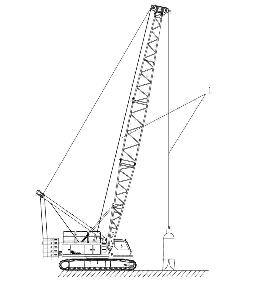
[0032] In the present invention, unless stated to the contrary, the used orientation words such as "up and down" generally refer to up and down in the vertical direction, and also refer to up and down shown in the drawings. The "locking device" in the present invention refers to the device used to fix and connect heavy loads such as crane hooks and grab buckets. Ability to lift or lower heavy loads while retracting the wire rope.

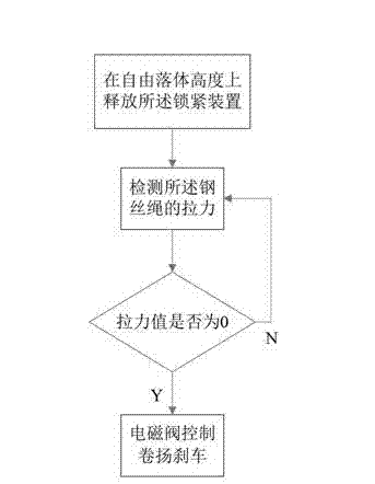
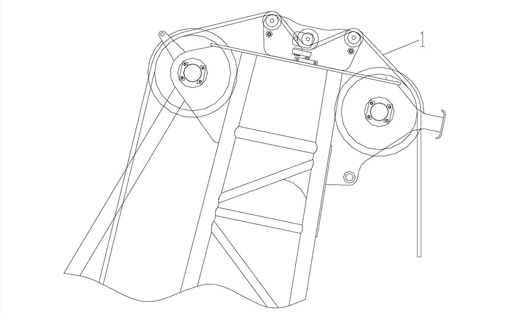
[0033] The invention provides a method for controlling free fall of a locking device of a crane. The crane includes a winch, a solenoid valve for controlling the brake of the winch, and a steel wire rope 1. One end of the steel wire ...


PUM


Abstract

The invention discloses a free-fall control method of a locking device of a crane. The control method comprises the following steps of: releasing the locking device on a free-fall height, and detecting a tensile force of a steel wire rope in the process; and when the tensile force is 0, controlling a hoist to brake by an electromagnetic valve. The invention further discloses a controller, a control system and a crane for realizing the method. By the technical scheme, an automatic detecting and controlling method is used to replace the method of judging and controlling the hoist to brake through a manual visual inspection method in the prior art; the brake time can be exactly grasped, and errors can be reduced, so that the potential security risks which possibly occur in free-fall brake can be reduced, and the whole process of the hoist to brake is safe and reliable; and the scheme does not depend on factors such as observation ability, response speed, working experience and operation number degree of an operator, so that the error operation caused by manual factors can be reduced.

Description

technical field [0001] The invention relates to the field of engineering machinery, in particular to a method for controlling free fall of a locking device of a crane, a controller for realizing the control method, a control system including the controller, and a crane. Background technique [0002] In the field of engineering technology, in some applications, such as the need to generate a large impulse, it is usually necessary to use lifting equipment to fix the heavy load of the locking device and lift it to a certain height, and then completely cancel the pulling force to make the locking The device and the weight load are left in free fall to generate the required momentum. [0003] For this kind of hoisting equipment, generally utilize the winch that has this locking device to carry free fall function. With the development of the crane industry, there are more and more hoisting equipment with this kind of winch to adapt to the application in more engineering fields. ...

Claims


Application Information

Patent Timeline
Patent Type & Authority Applications(China)
IPC IPC(8): B66D5/28B66C23/62B66C13/48
Inventor 詹纯新刘权丁慧智滕宏珍
Owner ZOOMLION HEAVY IND CO LTD
Why Eureka
Try Eureka