Yarn heater

A heating device and yarn technology, applied in the field of yarn heating devices, can solve the problems of increased power consumption of the heater and the like

Active Publication Date: 2012-10-17
TMT MACHINERY INC
View PDF11 Cites 8 Cited by
  • Summary
  • Abstract
  • Description
  • Claims
  • Application Information

AI Technical Summary

Problems solved by technology

As a result, the temperature in the incubator drops, and the power consumption

Method used


Image

  • Yarn heater
  • Yarn heater
  • Yarn heater

Examples


Embodiment Construction

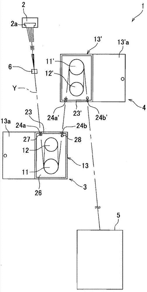
[0032] Preferred embodiments of the present invention will be described below. figure 1 It is a schematic structural diagram of the yarn manufacturing apparatus of this embodiment. Such as figure 1 As shown, the yarn manufacturing device 1 includes a spinning machine 2, an oil supply unit 6, two roller units 3 and 4 (yarn heating device), a winding machine 5, and the like.

[0033] The spinning machine 2 spins the yarn Y (so-called multifilament) composed of a plurality of single fibers discharged from the spinning spinneret 2a downward. The oil supply unit 6 attaches oil to the plurality of yarns Y spun from the spinning machine 2 and run. The roller units 3 and 4 stretch and feed the plurality of yarns Y spun from the spinning machine 2 and to which the oil agent is adhered while being heated. The winder 5 winds the plurality of yarns Y stretched and sent by the roller units 3 and 4 onto a bobbin (not shown).

[0034] In addition, among the configurations of the respecti...


PUM


Abstract

By improving the heat insulating efficiency in thermal insulation box, the power consumption of a heater for heating yarns fed from the yarn feeding roller is decreased. A roller unit 3 includes a godet roller 11, a separate roller 12, a thermal insulation box 13 housing the rollers 11 and 12, and a heat exchanger 30 provided outside the thermal insulation box 13. The heat exchanger 30 operates such that, as an exhaust fan 40 is driven, the air in the thermal insulation box 13 is exhausted through an inner tube 31. As an intake fan 41 is driven, the outside air passes through an outer tube 32 and then flows into the thermal insulation box 13 through a branched tube 34. At this stage, the heat exchanger 30 conducts heat exchange between the air running in the inner tube 31 and the air running in the outer tube 32.

Description

technical field [0001] The present invention relates to a yarn heating device for heating yarn. Background technique [0002] Patent Document 1 describes a spinning winder that stretches the yarn fed from the spinning section while being conveyed by a guide roller, and winds it up by a winder. The spinning winder of Patent Document 1 is provided with an oil supply device for applying an oil to a plurality of yarns spun from a spinning machine, and two guide rollers. Then, the plurality of yarns spun from the spinning machine and to which the oil agent is attached by the oil supply device are stretched between two guide rollers. [0003] Furthermore, Patent Document 2 describes a technique of using a guide roller as a heating roller. In addition, since the heating roller is housed in a box (insulation box), heat generated by the heating roller is less likely to escape from the interior of the insulation box to the outside. [0004] [Patent Document 1] Japanese Unexamined P...

Claims


Application Information

Patent Timeline
IPC IPC(8): D01H13/28
CPCD02J13/005D01D10/02
Inventor 加贺田翔
Owner TMT MACHINERY INC
Why Eureka
Try Eureka