Electronic control high-pressure common-rail fuel injection system for V-shaped diesel engine

A fuel injection system and high-pressure common rail technology, applied in fuel injection control, fuel injection device, electrical control, etc., can solve the problem that diesel engines cannot meet the needs of national development, and achieve high reliability, reduce emissions, and improve economy. Effect

Inactive Publication Date: 2012-10-17
WUXI KIPOR POWER CO LTD
View PDF6 Cites 18 Cited by
  • Summary
  • Abstract
  • Description
  • Claims
  • Application Information

AI Technical Summary

Problems solved by technology

[0002] With the country's increasing emphasis on environmental protection, traditional diesel eng

Method used


Image

  • Electronic control high-pressure common-rail fuel injection system for V-shaped diesel engine
  • Electronic control high-pressure common-rail fuel injection system for V-shaped diesel engine

Examples


Embodiment 1

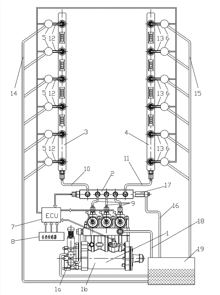
[0013] like figure 1 As shown, the electronically controlled high-pressure common rail fuel injection system in Embodiment 1 is used on a V-type 12-cylinder diesel engine. The electronically controlled high-pressure common rail fuel injection system is mainly composed of a common rail pump 1, a common rail pipe distributor 2, a first common rail pipe 3, a second common rail pipe 4, a first fuel injector 5, and a second fuel injector 6 , electronic control unit (ECU) 7, various sensors 8, high pressure oil pipe 9, first high pressure main oil pipe 10, second high pressure main oil pipe 11, second high pressure branch oil pipe 13, first oil return pipe 14, second oil return pipe 15 , the third oil return pipe 16, the pressure limiting valve part 17, the fourth oil return pipe 18 and the oil tank 19 and other components.

[0014] like figure 1 As shown, the oil inlet of the common rail pump 1 is connected to the oil tank 19, and the oil outlet of the common rail pump 1 is conne...

Embodiment 2

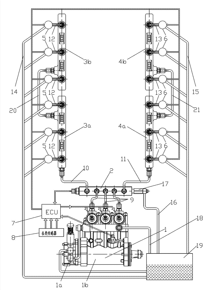
[0019] like figure 2 As shown, the electronically controlled high-pressure common rail fuel injection system in Embodiment 2 is also used in the V-type 12-cylinder diesel engine. The only difference between it and Embodiment 1 is that the first common rail pipe 3 is mainly composed of the first front common rail pipe 3a, the first rear common rail pipe 3b and the first high-pressure connecting oil pipe 20, and the first front common rail pipe 3a passes through The first high-pressure main oil pipe 10 is connected to the common rail pipe distributor 2, and the first rear common rail pipe 3b is connected to the first front common rail pipe 3a through the first high-pressure connecting oil pipe 20; the second common rail pipe 4 is mainly composed of the second front common rail pipe 3b. The rail pipe 4a, the second rear common rail pipe 5b and the second high-pressure connecting oil pipe 21 are composed, the second front common rail pipe 4a is connected with the common rail pipe...


PUM


Abstract

The invention relates to an electronic control high-pressure common-rail fuel injection system for a V-shaped diesel engine. A fuel inlet of a common-rail pump is connected with a fuel tank; a fuel outlet of the common-rail pump is connected with a common-rail tube distributor through a high-pressure fuel tube; the common-rail tube distributor is respectively connected with a first common-rail tube and a second common-rail tube through a first high-pressure main fuel tube and a second high-pressure main fuel tube; the first common-rail tube is arranged on one side of a first line of cylinders of the V-shaped diesel engine; first fuel injectors on cylinders of the first line of cylinders are respectively connected with the first common-rail tube through first high-pressure branch fuel tubes; fuel return openings of the first fuel injectors are connected with the fuel tank through first fuel return tubes; the second common-rail tube is arranged on one side of a second line of cylinders of the V-shaped diesel engine; second oil injectors on cylinders of the second line of cylinders are respectively connected with the second common-rail tube through second high-pressure branch fuel tubes; and fuel return openings of the second fuel injectors are connected with the fuel tank through second fuel return tubes. By utilizing the V-shaped diesel engine, emission is reduced, economical efficiency is increased, operation control is automatic, and reliability is high.

Description

technical field [0001] The invention relates to a fuel injection system, in particular to an electronically controlled high-pressure common rail fuel injection system suitable for a V-type diesel engine and used for delivering fuel to an internal combustion engine. Background technique [0002] As the country pays more and more attention to environmental protection, the traditional diesel engine with mechanical fuel injection system can no longer meet the needs of the country's development. Diesel engines using electronically controlled high-pressure common rail fuel injection systems have become the research direction of various engine manufacturers. [0003] The main feature of the electronically controlled high-pressure common rail fuel injection system is that the high pressure in the common rail cavity is directly used for injection, and the high pressure in the common rail cavity is continuously high, and the driving torque required by the high pressure oil pump is muc...

Claims


Application Information

Patent Timeline
IPC IPC(8): F02M41/02F02M55/02F02D41/04
CPCF02M41/02F02M55/025F02M41/04F02M55/02F02M63/0295
Inventor 肖亨琳韦海
Owner WUXI KIPOR POWER CO LTD
Why Eureka
Try Eureka