Eureka AIR delivers breakthrough ideas for toughest innovation challenges, trusted by R&D personnel around the world.

Tunnel curing barn adopting humiture subdivision control of alternate wind direction

A segmented control, tunnel-type technology, applied in the field of tunnel-type baking rooms, can solve the problems of not being able to achieve the optimal baking temperature curve and humidity curve, and unable to take care of the temperature and humidity changes in the tunnel, so as to shorten the heat conduction distance and shorten the baking time. The effect of reducing the baking time and heat conduction distance

Active Publication Date: 2014-07-16
北京华珍烘烤系统设备工程有限公司
View PDF6 Cites 1 Cited by
  • Summary
  • Abstract
  • Description
  • Claims
  • Application Information

AI Technical Summary

Problems solved by technology

When the high-temperature hot air at the inlet enters the tunnel and contacts the material, it evaporates the moisture of the material, the temperature of the hot air drops, and the humidity increases, so the baking environment (temperature, humidity) of the downwind material is very different from that of the upwind material, and the material is in the whole baking process. , the baking environment from entering to exiting is changing at any time, the parameters that can be controlled are only the temperature of the incoming air, the wind speed, it is impossible to achieve the best combination of baking temperature curve and humidity curve, dehydration speed, let alone take care of the tunnel Changes in temperature and humidity due to changes in material loading

Method used

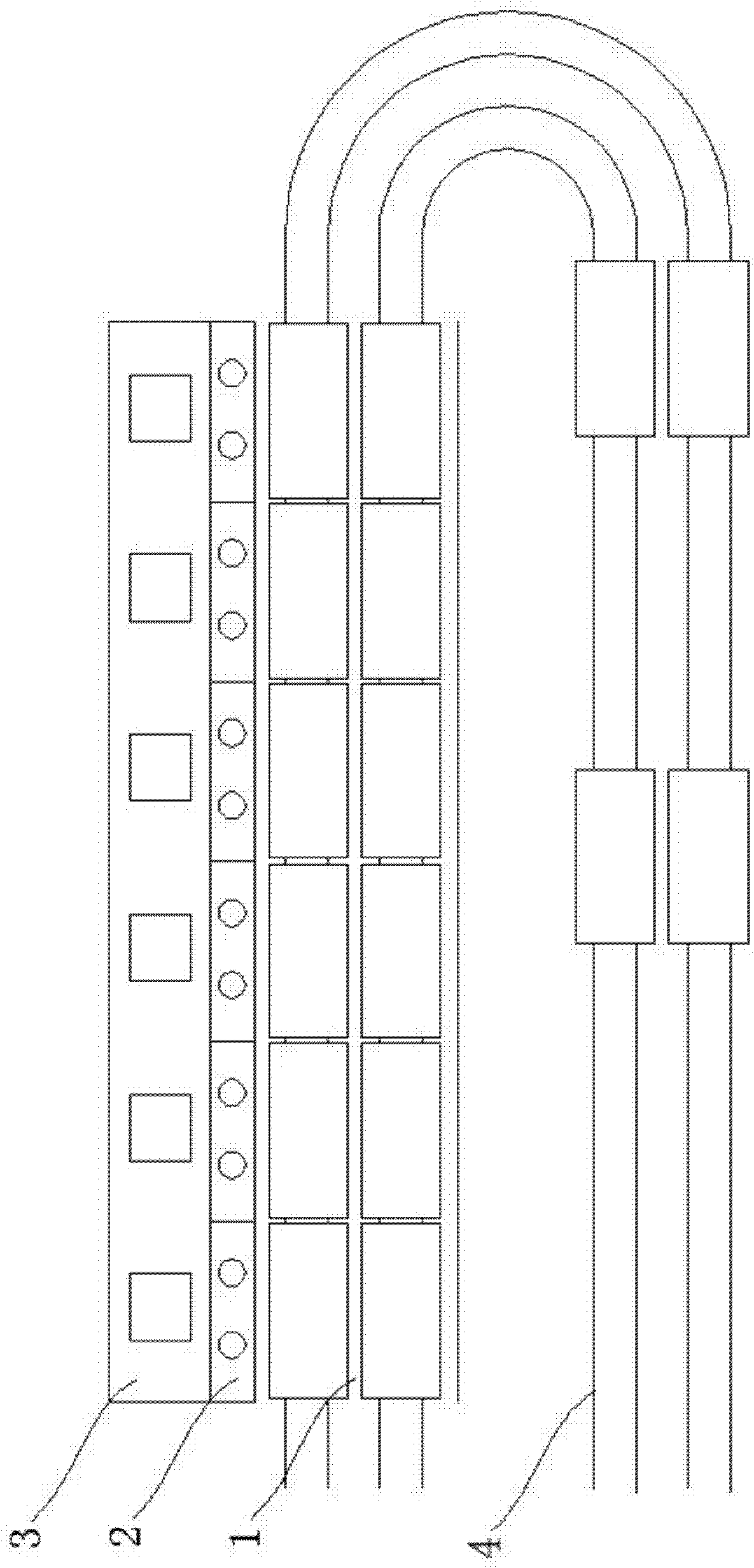
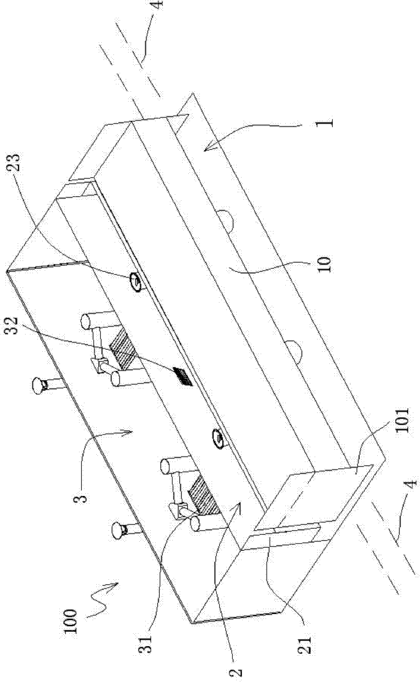
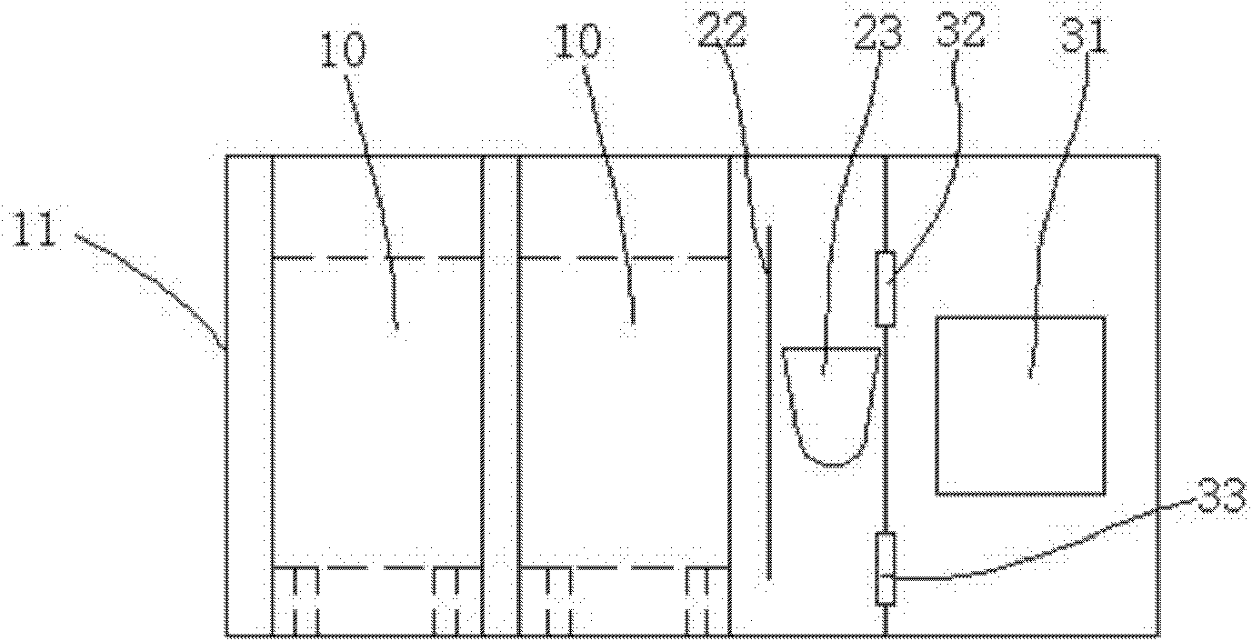

Image

  • Tunnel curing barn adopting humiture subdivision control of alternate wind direction
  • Tunnel curing barn adopting humiture subdivision control of alternate wind direction
  • Tunnel curing barn adopting humiture subdivision control of alternate wind direction

Examples


Embodiment Construction

[0025] Relevant present invention is for reaching above-mentioned purpose of use and effect and the technical means adopted, presents preferred feasible embodiment, and cooperates as shown in the accompanying drawings, detailed description is as follows:

[0026] Such as figure 1 As shown, the present invention is a tunnel-type barn with segmental control of temperature and humidity using alternating wind directions. The tunnel-type barn is sequentially distributed with a plurality of independent work rooms, and each work room includes a barn room 1. An air-mixing layer 2 and a hot-air room 3, wherein each workshop can be provided with a hot-air room 3, or multiple workshops can share at least one hot-air room 3. There is at least one material trolley 10 passing through the baking room 1 each time, and each material trolley 10 moves a distance between the baking rooms. A track 4 is also arranged in the said baking room 1, which runs through each working room. The material tr...


PUM


Abstract

Disclosed is a tunnel curing barn adopting humiture subdivision control of alternate wind direction, and the tunnel curing barn is formed by a plurality of work cells, which are penetrated through and connected by a track. Each work cell comprises a baking cell, an air-mixing layer and a hot air cell. Each work cell is provided with one hot air cell or the plurality of work cells share at least one hot air cell. The air-mixing layer is located between the baking cell and the hot air cell. Material trolleys which pass through the baking cells respectively move a distance of one baking cell every time, and the material trolleys are used for being filled with materials to be baked. A circulating fan is installed in the air-mixing layer to produce an ascending airflow or a descending airflow. A heating or heat exchanging device is disposed in the hot air cell. The whole tunnel curing barn is separated into a plurality of independent work cells by separating plates which are provided at the front end and the rear end of the material trolleys in the baking cells, and each work cell forms an independent hot air self-circulating system. The material trolleys on the track move forward at intervals and are capable of moving at fixed time and fixed quantity and staying in different work cells for drying according to temperature and humidity required by materials at different times.

Description

technical field [0001] The invention relates to a tunnel-type curing barn, in particular to a tunnel-type curing barn adopting segmental control of temperature and humidity in alternate wind directions. Background technique [0002] Tunnel-type hot air drying is a drying method that has been used for many years. High-temperature hot air enters from one end of the tunnel and exits from the other end of the tunnel. Material enters one end and exits the other, lining up in the tunnel. When the high-temperature hot air at the inlet enters the tunnel and contacts the material, it evaporates the moisture of the material, the temperature of the hot air drops, and the humidity increases, so the baking environment (temperature, humidity) of the downwind material is very different from that of the upwind material, and the material is in the whole baking process. , the baking environment from entering to exiting is changing at any time, the parameters that can be controlled are only t...

Claims


Application Information

Patent Timeline
Patent Type & Authority Patents(China)
IPC IPC(8): F26B15/10F26B21/06F26B25/00
Inventor 郭倞闿
Owner 北京华珍烘烤系统设备工程有限公司
Why Eureka
Eureka Blog
Learn More