Infrared sequence thermography analysis method for impact defects of carbon fiber composite material

A composite material and analysis method technology, applied in the field of ultrasonic infrared nondestructive testing defect quantitative analysis, can solve the problems of different loss, not yet formed, insufficient theoretical basis, etc., to achieve the effect of correcting gradient error, improving effectiveness and accuracy

Inactive Publication Date: 2012-10-17
BEIHANG UNIV
View PDF2 Cites 10 Cited by
  • Summary
  • Abstract
  • Description
  • Claims
  • Application Information

AI Technical Summary

Problems solved by technology

Defect splicing technology has become a relatively new angle of inquiry in domestic and foreign research. However, due to insufficient theoretical basis and other reasons, a complete set of methods has not yet been formed.
[0005] At the same time, in the actual experiment process, especially in the active thermal image non-destructive testing experiment, as shown in Figure 1, the thermal excitation source 1 is located directly above the specimen 2, so the dete

Method used


Image

  • Infrared sequence thermography analysis method for impact defects of carbon fiber composite material
  • Infrared sequence thermography analysis method for impact defects of carbon fiber composite material
  • Infrared sequence thermography analysis method for impact defects of carbon fiber composite material

Examples


Embodiment Construction

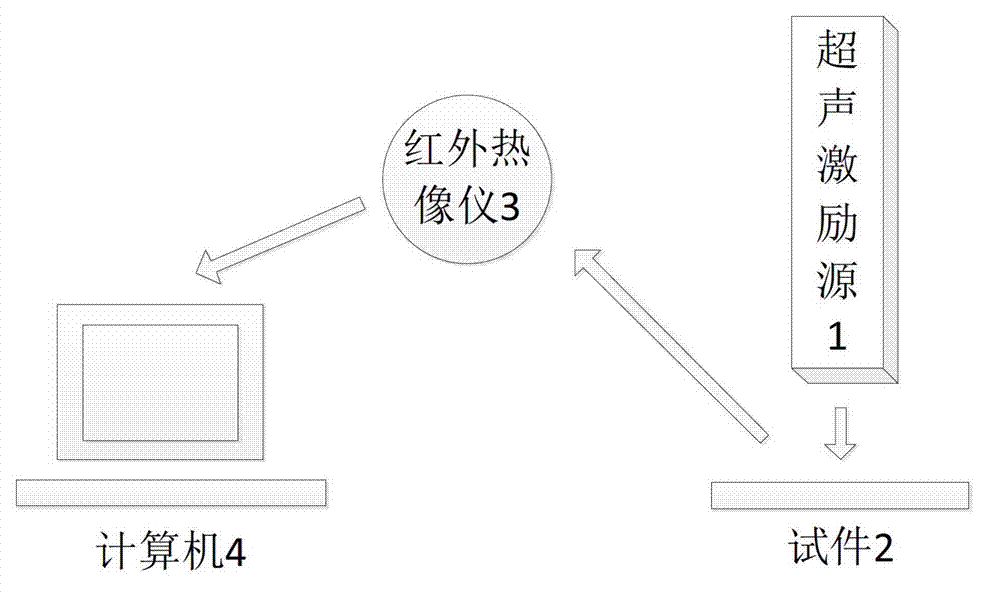
[0024] The research object of the present invention comes from the non-destructive testing experiment of ultrasonic infrared thermal imaging. The experimental system is shown in Figure 1. The viewing angle is aimed at the test piece 2, and the infrared camera 3 is connected to the computer 4 for data transmission. The ultrasonic excitation source 1 generates thermal excitation on the test piece 2, and the detected material with defects produces different temperature field distributions on the surface due to the difference in internal damage, and the infrared thermal imager 3 is used to obtain the infrared heat map during the heating or cooling process synchronously, And transmit it to the computer 4 for recording, and then process the recorded infrared sequence heat map, and further analyze the defects on the test piece.

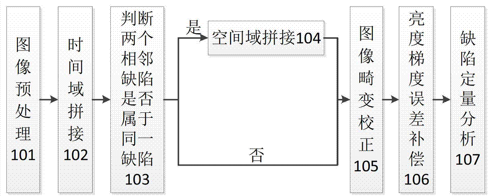
[0025] As shown in Figure 2, the infrared sequence heat map analysis method of the carbon fiber composite material impact defect comprises the following ste...


PUM


Abstract

The invention belongs to the field of ultrasonic and infrared nondestructive detection and quantitative analysis of defects, and specifically relates to a method for splicing of impact defects on a carbon fiber composite material laminated sheet and compensation of infrared thermal imager visual angle error. Impact defects on a composite material are discontinuous defects in infrared thermal image information shown in ultrasonic and infrared nondestructive detection tests, and problem of the discontinuous defects is solved with the method of the present invention. According to the method, a filtering pre-treatment is performed on an infrared sequence thermography; defect feature fusion is performed in a time domain; defect splicing analysis is performed in a spatial domain, and then defect splicing is performed, wherein the visual angle problem of an infrared thermal imager and a tested sample is considered, and image distortion and brightness gradient error caused by the infrared thermal imager visual angle are analyzed, corrected and compensated; and finally, quantitative analysis is performed on the defects. With the present invention, the splicing problem of the discontinuous defects is effectively solved, and the error is corrected so as to obtain efficient and accurate quantitative analysis data.

Description

technical field [0001] The invention belongs to the field of quantitative analysis of ultrasonic infrared non-destructive testing defects, and in particular relates to a defect splicing of impact defects on a carbon fiber composite material laminate and a viewing angle error compensation method of an infrared thermal imager. Background technique [0002] Ultrasonic infrared non-destructive testing technology has received extensive attention in the defect detection of composite materials. The basic principle is to generate thermal excitation on the tested material through the ultrasonic excitation source, and the tested material with defects will produce different temperature field distributions on the surface due to the difference in internal damage. The infrared heat map of the measured material is processed by digital image processing technology, and then the defect is analyzed by quantitative analysis method to obtain the size information of the defect. [0003] Defect d...

Claims


Application Information

Patent Timeline
IPC IPC(8): G01N21/88
Inventor 杨波罗晶程龙郑捷
Owner BEIHANG UNIV
Why Eureka
Try Eureka