
Solid-state imaging device and electronic apparatus

A solid-state imaging device and charge technology, which is applied to electric solid-state devices, semiconductor devices, radiation control devices, etc., can solve problems such as sensitivity decline, optical performance changes, and low light transmittance, and achieve the effect of preventing sensitivity decline.

Inactive Publication Date: 2012-10-17
SONY SEMICON SOLUTIONS CORP
View PDF10 Cites 12 Cited by
  • Summary
  • Abstract
  • Description
  • Claims
  • Application Information

AI Technical Summary

Problems solved by technology

However, in the current state, ITO used as a material for transparent electrodes has low light transmittance, and has a problem of decreased sensitivity, and causes changes in optical properties due to large film thickness

Method used


Image

  • Solid-state imaging device and electronic apparatus
  • Solid-state imaging device and electronic apparatus
  • Solid-state imaging device and electronic apparatus

Examples


no. 1 example

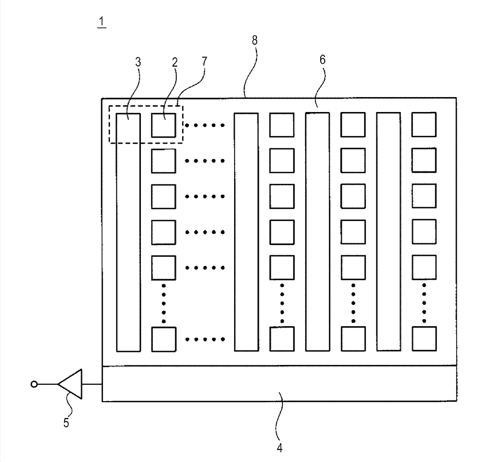
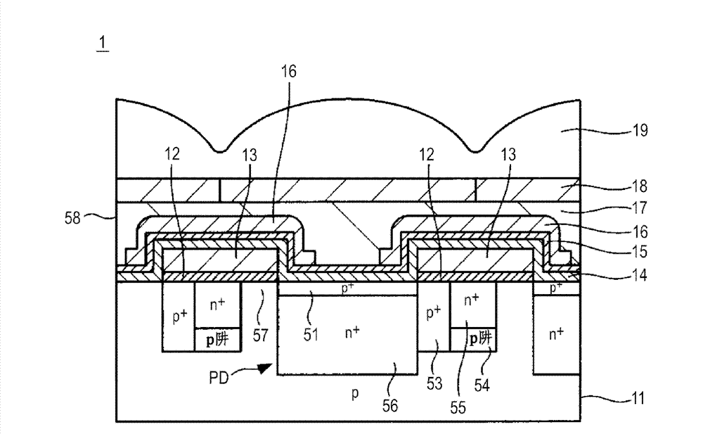
[0048] 1. First Embodiment: Example of a solid-state imaging device formed by bringing a transparent electrode into direct contact with a substrate

no. 2 example

[0049] 2. Second embodiment: Example of forming a light-adjustable laminated film on the upper part of a solid-state imaging device

no. 3 example

[0050] 3. Third embodiment: Example of a solid-state imaging device in which a dimming laminated film formed of an electrochromic layer is formed directly above an on-chip lens


PUM


Abstract

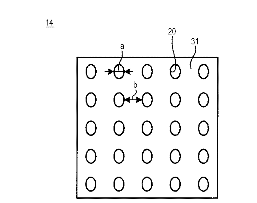
The invention discloses a solid-state imaging device and an electronic apparatus. A solid-state imaging device includes: a substrate; a photoelectric conversion unit that is formed on the substrate and generates signal charge in correspondence with a light amount of incident light; and a transparent electrode that is formed in an upper portion of the substrate and includes a first area formed from a nano carbon material and a second area that is brought into contact with the first area and has light transmittance higher than that of the first area. The invention provides the solid-state imaging device, in which a transparent electrode is formed, capable of solving the problems of a decrease in the transmittance of the transparent electrode and variations in the optical characteristic due to the film thickness.

Description

[0001] Cross References to Related Applications [0002] This application contains subject matter related to that disclosed in Japanese Priority Patent Applications JP 2011-072177 and JP 2011-271364 filed with the Japan Patent Office on March 29, 2011 and December 12, 2011, respectively, and the above-mentioned Japanese The entire content of the priority application is incorporated herein by reference. technical field [0003] The present invention relates to a solid-state imaging device including a transparent electrode, an electronic device including the solid-state imaging device, and an electronic device including the transparent electrode. Background technique [0004] A solid-state imaging device represented by a charge-coupled device (CCD) image sensor or a complementary metal-oxide-semiconductor (CMOS) image sensor includes a photoelectric conversion unit formed on the light-receiving surface side of a substrate and a charge transfer portion. of photodiodes. In suc...

Claims


Application Information

Patent Timeline
Patent Type & Authority Applications(China)
IPC IPC(8): H01L27/146H04N5/335H04N25/00H04N23/40
CPCH01L27/14625H01L27/14685H01L27/14621H01L27/14806H01L27/14643H01L27/14623H04N25/51H01L27/146
Inventor 出羽恭子清水圭辅小林俊之木村望
Owner SONY SEMICON SOLUTIONS CORP
Learn More