Infrared touch control method and system for extractor hood
A technology of infrared touch and range hood, which is applied in the field of kitchen and bathroom appliances, can solve the problems of large standby power consumption, large working current, severe heat dissipation, etc., and achieve the effects of low standby power consumption, small heat generation and high reliability
- Summary
- Abstract
- Description
- Claims
- Application Information
AI Technical Summary
Problems solved by technology
Method used
Image
Examples
Embodiment 1
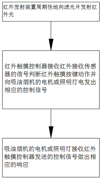
[0049] Such as figure 1 As shown, an infrared touch control method of a range hood comprises the following steps:
[0050] S1: The infrared emitting device periodically emits infrared light to the filter;
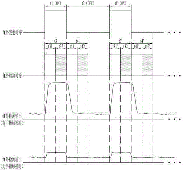
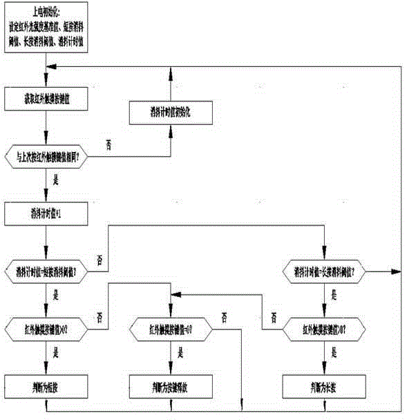
[0051] S2: Each infrared receiving sensor corresponds to a touch area on the filter to form a virtual infrared touch button. After the infrared touch button is touched by a finger, the infrared receiving sensor periodically collects the infrared light reflected by the corresponding touch area on the filter. The optical signal is converted into an electrical signal and sent to the infrared touch controller. The infrared touch controller judges the action of the infrared touch button on the filter according to the received signal, and sends electricity to the motor of the range hood or the lighting lamp according to the action of the infrared touch button. Send corresponding control signals;
[0052] S3: The motor or lighting lamp of the range hood receives the control sign...
Embodiment 2
[0072] like Figure 5-6 As shown, an infrared touch control system of a range hood includes an infrared touch switch assembly control substrate 26 installed on the range hood body, an optical filter 21, an infrared emitting device 22, a plurality of infrared receiving sensors 24 and an infrared touch Controller 25; Infrared emitting device 22 and infrared receiving sensor 24 are installed on the infrared touch switch assembly control substrate 26, and optical filter 21 is pasted on the infrared receiving sensor 24, and each infrared receiving sensor 24 is corresponding on the optical filter 21 A touch area constitutes a virtual infrared touch key, and the infrared emitting device 22 is positioned at the end face of the optical filter 21 so that its light-emitting direction is perpendicular to the end face of the optical filter 21 and parallel to the photosensitive surface of the infrared receiving sensor 24. The touch controller 25 is electrically connected, and the infrared t...
PUM
 Abstract
Description
Claims
Application Information
 - R&D
- Intellectual Property
- Life Sciences
- Materials
- Tech Scout
- Unparalleled Data Quality
- Higher Quality Content
- 60% Fewer Hallucinations
Browse by: Latest US Patents, China's latest patents, Technical Efficacy Thesaurus, Application Domain, Technology Topic, Popular Technical Reports.
© 2025 PatSnap. All rights reserved.Legal|Privacy policy|Modern Slavery Act Transparency Statement|Sitemap|About US| Contact US: help@patsnap.com


