Variable reluctance motor and rotor structure thereof

A variable reluctance, rotor technology, applied in the shape/style/structure of the magnetic circuit, the rotating parts of the magnetic circuit, the static parts of the magnetic circuit, etc. Variable reluctance motor limitation and other problems, to achieve the effect of improving vibration and noise problems, reducing iron loss, and improving efficiency

Inactive Publication Date: 2012-10-17
周智庆
View PDF6 Cites 8 Cited by
  • Summary
  • Abstract
  • Description
  • Claims
  • Application Information

AI Technical Summary

Problems solved by technology

[0004] However, due to the inherent defects of traditional variable reluctance motors (torque fluctuation, large iron loss and magnetic loss, and large noise), the application of variable reluctance motors is greatly limited; in order to improve the defects of traditional variable reluctance motors, countries around the world Scholars have conducted active research on the root causes of its defects and improvement measures
[0005] Among them, in order to reduce its torque fluctuation and its vibration and noise level, the Chinese invention patent application: switched reluctance motor (patent application number: 200680043128.X) improves the noise level by optimizing the rotor magnetic pole structure; and the Chinese invention patent application: double stator switch The reluctance motor (patent application number: 200510037635.X) adopts a double stator structure to improve its torque fluctuation, but the technical solutions adopted by the above two invention patent applications have not improved the source of vibration and noise, that is, too large a diameter is also a path for useless work. Xiang Li

Method used


Image

  • Variable reluctance motor and rotor structure thereof
  • Variable reluctance motor and rotor structure thereof
  • Variable reluctance motor and rotor structure thereof

Examples


Embodiment Construction

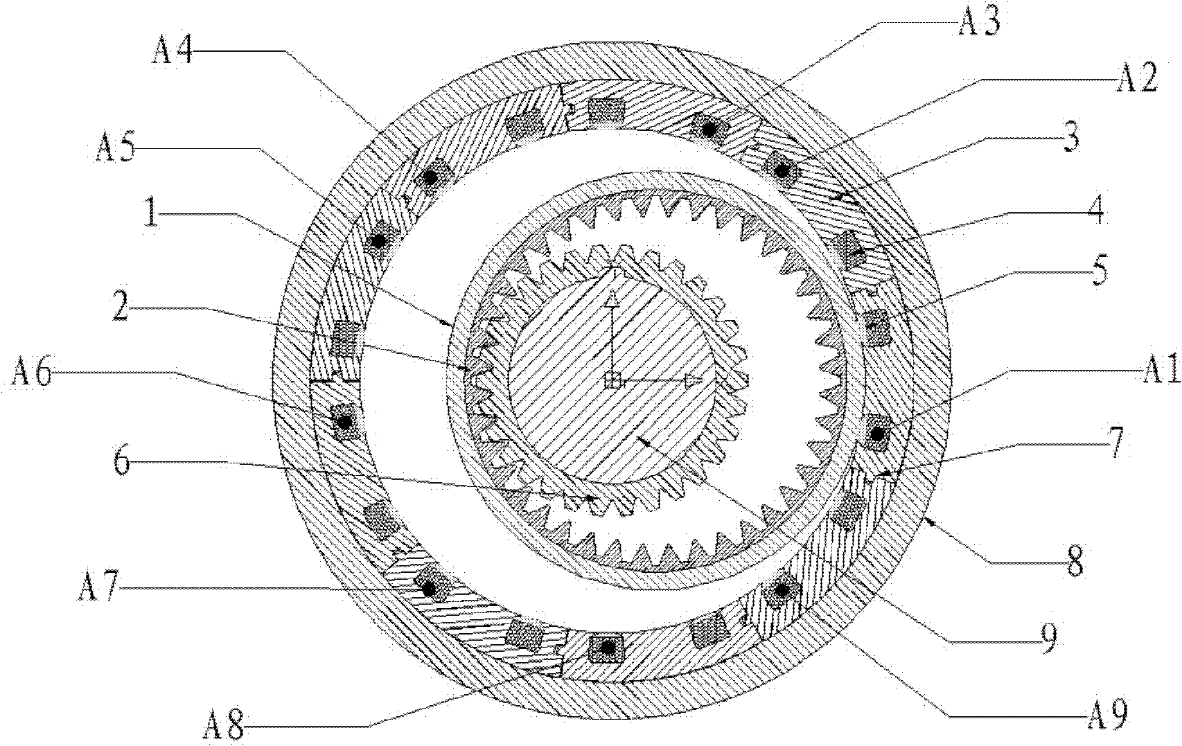
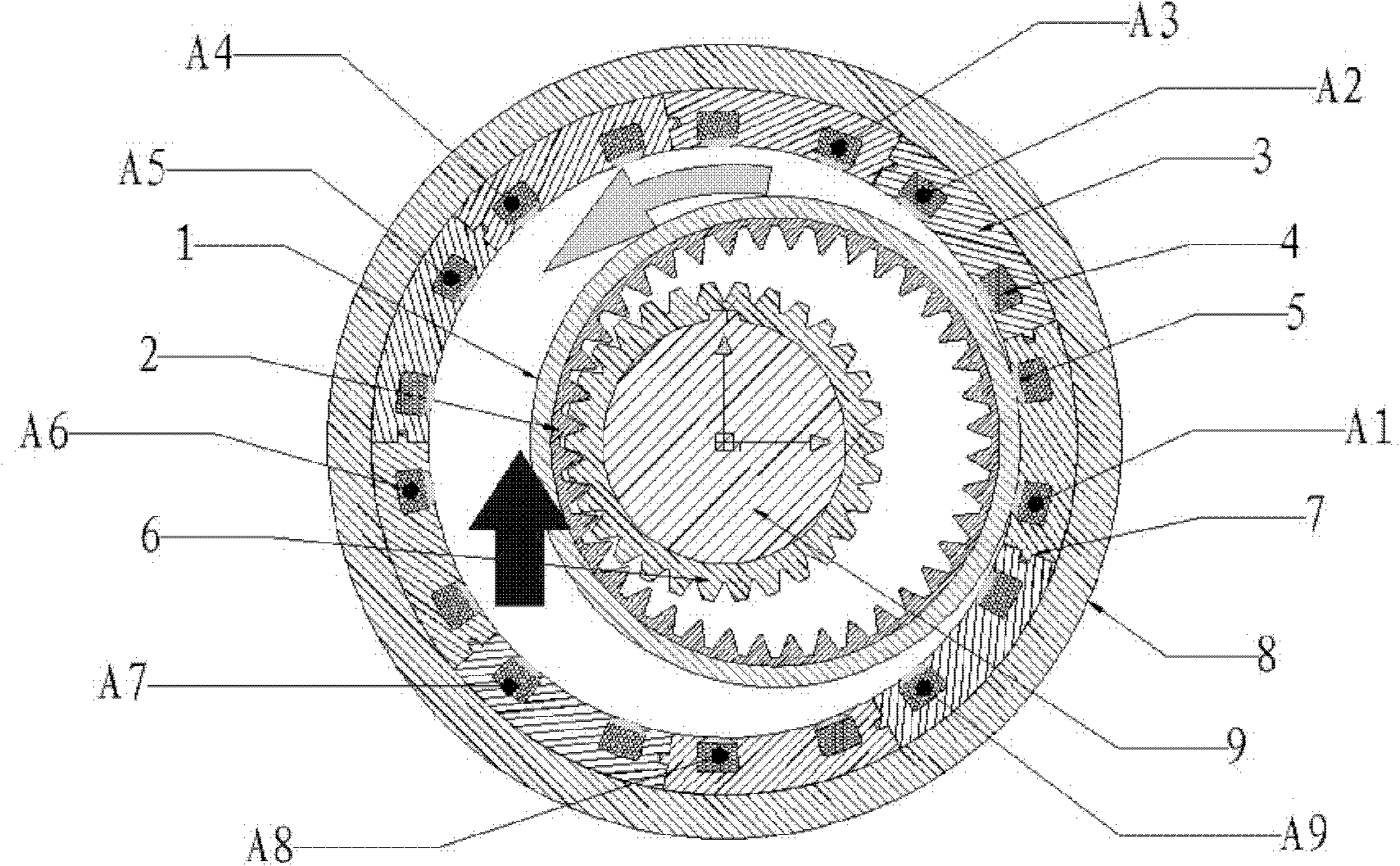
[0031] refer to figure 1 , the figure is a schematic structural diagram of a specific embodiment of the variable reluctance motor of the present invention.

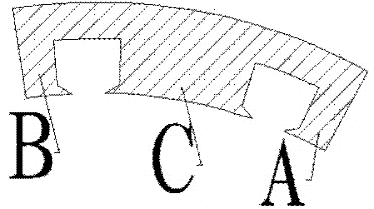
[0032] The variable reluctance motor of this embodiment includes a stator part, a rotor part and an excitation winding 4. In addition, in this embodiment, the stator part includes a plurality of E-shaped stator segments 3, and the plurality of E-shaped stator segments 3 are The circumferential direction is evenly arranged, and the inner circular surface of the stator can be cylindrical or drum-shaped. The above stator segment 3 is installed in the inner circular surface of the motor base 8, and each E-shaped stator segment assembly is spaced from each other by a certain air gap 7 Or evenly installed along the inner circle of the machine base without air gap. In the specific implementation, the E-shaped stator segment 3 components can be laminated with soft magnetic material sheets, and the openings of the two slots of the...


PUM


Abstract

The invention discloses a variable reluctance motor and a rotor structure thereof. A stator portion of the variable reluctance motor comprises a plurality of E-shaped stator segments; and an inner circular surface of the stator is in a cylindrical surface shape or a drum shape. A rotor portion is an annular eccentric rotor in a cylindrical shape or a drum shape; the ring-type eccentric rotor in the cylindrical shape includes an inner ring and an outer ring, wherein the outer ring is a magnet collecting ring. The magnetic collection capability of the outer ring of the ring-type eccentric rotor in the cylindrical shape is utilized, thereby reducing the magnetic flux leakage and improving efficiency. When a load works, magnetic forces generated between the ring-type eccentric rotor in the cylindrical shape and the E-shaped stator segments are mostly used for working. Meanwhile, because the direction of the magnetic field of the stator is almost not changed, the iron loss is substantially reduced; due to application of the radial force to the working and the structure of the ring-type eccentric rotor in the cylindrical shape, the output torque, compared with that of the traditional variable reluctance motor, is more stable and thus the vibration and noises are reduced. In addition, the ring-type eccentric rotor in the cylindrical shape has the light weight and the dynamic performance of the rotor is superior to that of a traditional switch reluctance motor.

Description

technical field [0001] The invention relates to a motor, in particular to a variable reluctance motor and its rotor structure which are eccentric relative to the stator and the rotor of the output shaft. Background technique [0002] Variable reluctance motor is a new type of speed regulating motor. The speed regulating system has the advantages of both DC and AC speed regulating systems. It is the latest generation of stepless speed regulating system following variable frequency speed regulating system and brushless DC motor speed regulating system. It has a simple and sturdy structure, a wide speed regulation range, excellent speed regulation performance, high efficiency in the entire speed regulation range, high system reliability, and is suitable for high-speed operation. [0003] Generally, the variable reluctance motor includes a stator installed in the frame and a rotor that rotates relative to the stator. The stator and the rotor have protruding magnetic poles spaced...

Claims


Application Information

Patent Timeline
Patent Type & Authority Applications(China)
IPC IPC(8): H02K1/12H02K1/22H02K1/24
Inventor 周智庆杨军平
Owner 周智庆
Why Eureka
Try Eureka