Air bag catheter

A technology of balloon catheters and balloons, which is applied in the direction of balloon catheters, stents, etc., can solve problems such as bending and distortion of rigid transition parts, and achieve the effect of improving flexibility and supporting stability

Active Publication Date: 2012-10-24
GOODMAN & COMPANY
View PDF6 Cites 7 Cited by
  • Summary
  • Abstract
  • Description
  • Claims
  • Application Information

AI Technical Summary

Problems solved by technology

In this case, the rigid transition part may be twisted (bent)

Method used


Image

  • Air bag catheter
  • Air bag catheter
  • Air bag catheter

Examples


Embodiment 1

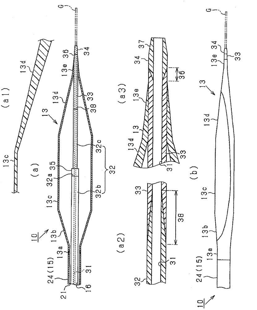
[0097] An inner layer with a thickness of 0.016 mm made of high-density polyethylene (Petrothene LR7340 from M.holland), a middle layer with a thickness of 0.004 mm made of low-density polyethylene (Plexar PX3080 from Equistar), and a polyamide elastic A hollow tube having an outer layer with a thickness of 0.06 mm, an inner diameter of 0.42 mm, an outer diameter of 0.58 mm, and a length of 300 mm formed of a body (Pebax7033 from ARKEMA Corporation).

[0098] A range of 10 mm from one end of the hollow tube was extended by passing an extending jig in which a circular hole with an inner diameter of 0.52 mm was formed with the mandrel for fixing the inner diameter inserted inward. Afterwards, the end portion of the extended side is cut off, thereby making the inner proximal region 32b having an inner diameter of 0.41 mm, an outer diameter of 0.55 mm, and a length of 290 mm, and a small diameter area 32 c of an inner diameter of 0.41 mm, an outer diameter of 0.52 mm, and a length ...

Embodiment 2

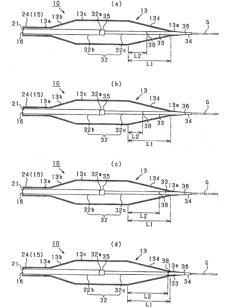
[0102] The inner tube 16 was produced in the same manner as in Example 1, except that the length from the above-mentioned stepped portion 32 a to the distal end of the above-mentioned inner proximal tube 32 was 10 mm.

Embodiment 3

[0104] The inner tube 16 was produced in the same manner as in Example 1, except that the length from the above-mentioned stepped portion 32 a to the distal end of the above-mentioned inner proximal tube 32 was 12 mm.


PUM


Abstract

The present invention provides an air bag catheter increasing the flexibility of a far position end portion, wherein inside the air bag catheter, the rigid optimization of an area provided with the air bag is realized. The air bag catheter (10) is provided with an outer side pipe (15) and an inner side pipe (16), wherein the inner side pipe (16) is arranged to extend to the position of a far position side compared with the outer side pipe (15) and provided with an air bag (13) in a manner of covering the extended area from the outer side, and the inner side pipe (16) is provided with an inner side near position pipe (32) and an inner side middle pipe with a lower rigidity than the inner side near position pipe (32). Under such conditions, the far position end portion of the inner side near position pipe (32) is arranged at a position where the boundary of a far position side cone-shaped area (13d) and the far position side support area (13e) is near the near position side and the boundary of the straight pipe area (13c) of the air bag and the far position side cone-shaped area (13d) is near the far position side in the axial direction.

Description

technical field [0001] The present invention relates to a balloon catheter used for introducing into a living body when dilating a stenosis or blockage of a blood vessel. Background technique [0002] Currently, balloon catheters are used in the treatment of PTA (Percutaneous Transluminal Angioplasty) or PTCA (Percutaneous Transluminal Coronary Angioplasty) and the like. The balloon catheter includes a catheter tube and a balloon fixed to a distal end side of the catheter tube. [0003] As such a balloon catheter, for example, Patent Document 1 discloses a configuration in which a flexible distal end piece is provided across a predetermined range from the distal end toward the proximal side in order to improve the flexibility of the distal end. Figure 7 An example of this configuration is shown in . [0004] like Figure 7 As shown, the balloon catheter 80 includes a catheter tube 81 and a balloon 82 . The catheter tube 81 includes an outer tube 83 and an inner tube 84 pe...

Claims


Application Information

Patent Timeline
Patent Type & Authority Applications(China)
IPC IPC(8): A61M25/10A61F2/958
Inventor 杉浦寿史小柳贺亮
Owner GOODMAN & COMPANY
Why Eureka
Try Eureka