Working roller considering both convexity and edge drop control of strip steel and design method for roller shape of working roller

A strip crown, work roll technology, applied in manufacturing tools, metal processing equipment, rolls, etc., can solve the problem of not being suitable for hot rolling, and achieve the effect of reducing the amount of trimming, increasing the yield, and improving the quality of the shape.

Active Publication Date: 2012-10-24
SHOUGANG CORPORATION
View PDF10 Cites 25 Cited by
  • Summary
  • Abstract
  • Description
  • Claims
  • Application Information

AI Technical Summary

Problems solved by technology

The work roll disclosed by the Chinese patent with publication number CN201231246 and the work roll disclosed by CN101367092 are suitable for edge drop control when cold rolling silicon steel, but are not suitable for hot rolling

Method used


Image

  • Working roller considering both convexity and edge drop control of strip steel and design method for roller shape of working roller
  • Working roller considering both convexity and edge drop control of strip steel and design method for roller shape of working roller
  • Working roller considering both convexity and edge drop control of strip steel and design method for roller shape of working roller

Examples


Embodiment

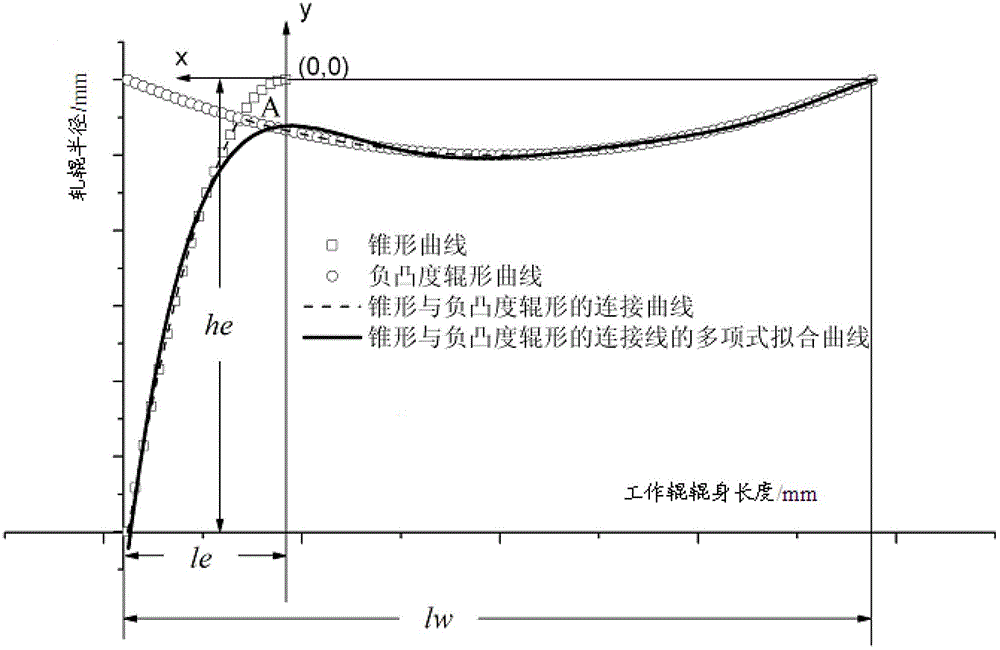
[0086] See attached figure 1 , the solid line is the roll shape curve equation of the work roll that takes into account the strip crown and edge drop control provided by the embodiment of the present invention:

[0087] R(x)=(-3.8142322×10 -19 ) x 6 +(4.3655522×10 -16 ) x 5 +(1.2677177×10 -13 ) x 4 +(-2.1984590×10 -10 ) x 3 +(1.1951196×10 -7 ) x 2 +(1.9948544×10 -5 )x+(-1.0089544×10 -1 ), x∈[0,1880]

[0088] in,

[0089] R(x), work roll body radius difference, mm,

[0090] x, the axial coordinate of the roll body, the origin of the coordinate is at one end of the roll, mm.

[0091] Wherein, the range of the roll shifting stroke of the work rolls may be 0-50 mm.

[0092] Wherein, the range of the roll shifting step length of the work rolls may be 5-10 mm.

[0093] See attached figure 1 According to the embodiment of the present invention, the roll shape design method of the work roll that takes into account both strip crown and edge drop control includes the fo...


PUM


Abstract

The invention discloses a working roller considering both a convexity and an edge drop control of strip steel, belonging to the technical field of steel rolling. A curve equation of a roller shape of the working roller is that R(x)=b6x6+b5x5+b4x4+b3x3+b2x2+b1x+b0, x belong to [ 0,1w]. When the working roller is used for rolling silicon steel by the working roller on a downstream rack in a refine rolling set of a heat continuous rolling production line, a rolling hot convexity can be offset by a negative convexity segmentation of a parabolic curve, the edge drop of strip steel can be controlled by the segmentation of a conical curve, so that hot silicon steel is enabled to have a cross section with excellent profile and shape, a good board condition is provided for subsequent cold rolling, quality of silicon steel board shape is increased, edge-cutting quantity of a finished product of silicon steel is reduced, and the finished product rate is improved. Additionally, the invention further discloses a design method for a roller shape of the working roller.

Description

technical field [0001] The invention relates to the technical field of steel rolling, in particular to a work roll and a roll shape design method that take into account strip crown and edge drop control. Background technique [0002] Since the lateral thickness difference of the silicon steel sheet directly affects the performance of the silicon steel laminate, the user has strict requirements on the shape quality of the silicon steel product, especially the lateral thickness difference. Therefore, it is usually necessary to strictly Control the crown and edge drop of silicon steel. Downstream users of electrical steel usually require edge drop values ​​below 10 μm. The production process of electrical steel is long and the production process is complex. Since there are many factors affecting the shape of electrical steel, there is a strong hereditary shape between processes. Therefore, it is necessary to control the crown and edge drop of the strip during the hot rolling s...

Claims


Application Information

Patent Timeline
Patent Type & Authority Applications(China)
IPC IPC(8): B21B27/02
Inventor 王晓东李飞李本海李彬王秋娜董立杰
Owner SHOUGANG CORPORATION
Why Eureka
Try Eureka