Microwave photocatalytic degradation reaction equipment

A catalytic degradation and reaction device technology, applied in chemical instruments and methods, water/sewage multi-stage treatment, mechanical oscillation water/sewage treatment, etc., can solve the problem of ultraviolet radiation blocking of electrodeless ultraviolet lamps, microwave photocatalytic reaction treatment device treatment Issues such as reduced efficacy

Inactive Publication Date: 2012-10-24
NINGBO UNIV
View PDF7 Cites 72 Cited by
  • Summary
  • Abstract
  • Description
  • Claims
  • Application Information

AI Technical Summary

Problems solved by technology

[0007] On the other hand, in the device structure expressed in the Chinese patent application whose publication number is CN102260003A, the outer wall of the quartz tube used for shielding the electrodeless ultraviolet lamp refers to the outer wall of the quartz tube. When dealing with industrial wastewater, it is inevitable to gradually accumulate fouling. Of course, the fouling substances are mainly inorganic impurities that are not easily touched by photocatalytic reactions. The fouling phenomenon formed by this mechanism is easy to be observed after the equipment has been running for a long time ; the fouling layer attached to the outer wall of the quartz tube, though only a thin layer, is enough to cause significant blocking to the ultraviolet radiation of the electrodeless ultraviolet lamp, which will lead to the actual treatment effectiveness of this microwave photocatalytic reaction treatment device It is greatly reduced; during the use of the laboratory scale, the above-mentioned fouling problem is not easy to detect, but on the industrial application scale, the fouling problem will undoubtedly be highlighted; Under the premise, it is another technical issue worthy of attention to immediately and effectively remove the fouling layer on the outer wall of the quartz tube and maintain the continuous high efficiency of the microwave photocatalytic treatment device.

Method used


Image

  • Microwave photocatalytic degradation reaction equipment

Examples


Embodiment Construction

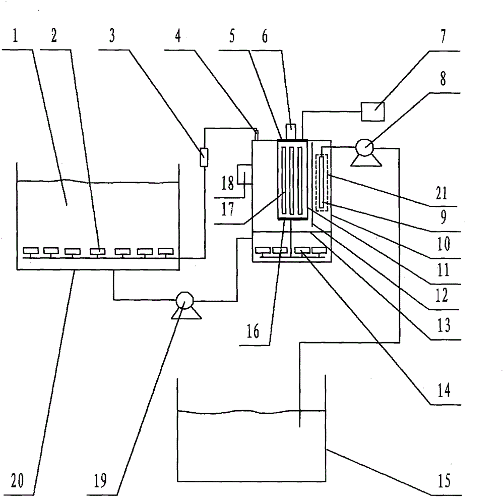
[0035] exist figure 1 In the shown embodiment of the present case, the structure of the device includes a reactor 10 whose outline is in the shape of a square barrel or a drum, and a water distribution plate 13 that contains many holes plate, the water distribution plate 13 divides the interior space of the reactor 10 into a microwave photocatalytic reaction chamber at the upper part and an aeration chamber at the lower part, and some microporous aeration heads 14 are installed in the aeration chamber, and , quartz tube 11, the erection position of this quartz tube 11 is the inside of the microwave photocatalytic reaction chamber, the two ends of this quartz tube 11 are equipped with sealing caps 5,16, and the sealing caps located at the two ends of the quartz tube are respectively All offer the interface that is used to connect trachea on the capping head 5,16, and, electrodeless ultraviolet lamp 17, this electrodeless ultraviolet lamp 17 also can be rod-shaped, and this elec...


PUM


Abstract

The invention relates to microwave photocatalytic degradation reaction equipment and belongs to the technical field of waste water treatment. The equipment provided by the invention aims at solving the problems that a membrane separation component is destroyed owning to thermal abrasion and the outer side of an electrodeless ultra violet lamp screen is scaled as the electrodeless ultraviolet lamp screen adopts a quartz tube in the prior art of microwave photocatalytic degradation on industrial waste water containing organic pollutant in a package manner. According to the invention, an organic matter membrane separation assembly is contained in a metal cage-shaped microwave shielding case, influence of microwave is isolated, and the absorption of metal particles and carbon particles, which are inevitably attached on the surface of the membrane separation assembly, to microwave energy is inhibited, so that thermal abrasion destruction on the membrane separation assembly is avoided; meanwhile, the cage-shaped microwave shielding case disclosed by the invention does not influence the function and operation of the membrane separation assembly; and an ultrasonic transducer is attached to the outer side of the wall face of a reactor, and the scale is immediately eliminated by high frequency ultrasonic wave through sound wave propagation by virtue of the wall of the reactor and a liquid mixture inside the wall.

Description

technical field [0001] The invention relates to a microwave photocatalytic degradation reaction device, which belongs to the technical field of CO2F wastewater treatment. Background technique [0002] Microwave photocatalytic degradation treatment technology, as an effective harmless treatment technology for industrial wastewater containing organic pollutants, has developed rapidly in recent years. [0003] Regarding the microwave photocatalytic degradation technology, as an example, refer to the Chinese patent application with publication number CN102260003A. [0004] The Chinese patent application with the publication number CN102260003A uses microwaves as the excitation source to excite the electrodeless ultraviolet lamp to emit ultraviolet rays, and irradiates the suspension mixed with photocatalyst titanium dioxide inside the liquid. The electrodeless ultraviolet lamp is shrouded and protected by a quartz tube. , an air pump continuously injects air into the inner cham...

Claims


Application Information

Patent Timeline
Patent Type & Authority Applications(China)
IPC IPC(8): C02F9/08C02F1/36
Inventor 任元龙李榕生李天华孙杰孔祖萍周汉坤干宁江晶覃海娇
Owner NINGBO UNIV
Why Eureka
Try Eureka