
H-shaped steel concrete column with high-strength spiral hoop and restraining high-strength wide flange

A technology of concrete column and spiral hoop, applied in the direction of columns, pillars, piers, etc., can solve the problems of unsatisfactory, low strength of stirrups, and inconvenient application of high-strength section steel, and achieve the effect of improving various indicators.

Inactive Publication Date: 2012-10-24
NORTH CHINA UNIV OF WATER RESOURCES & ELECTRIC POWER
View PDF5 Cites 5 Cited by
  • Summary
  • Abstract
  • Description
  • Claims
  • Application Information

AI Technical Summary

Problems solved by technology

The invention aims to solve the inconvenience of construction of commonly used I-shaped and H-shaped steel concrete columns (1:1≤height:width≤2:1), the thick concrete protective layer causes the medium-shaped steel in the column to not fully exert its bending resistance, the strength of the stirrup is low and the end There are a series of disadvantages such as the 135° hook is easy to loosen during an earthquake, resulting in unsatisfactory restraint on concrete and section steel, high-strength section steel is easy to buckle, and it is inconvenient to apply to engineering.

Method used


Image

  • H-shaped steel concrete column with high-strength spiral hoop and restraining high-strength wide flange
  • H-shaped steel concrete column with high-strength spiral hoop and restraining high-strength wide flange
  • H-shaped steel concrete column with high-strength spiral hoop and restraining high-strength wide flange

Examples


Embodiment Construction

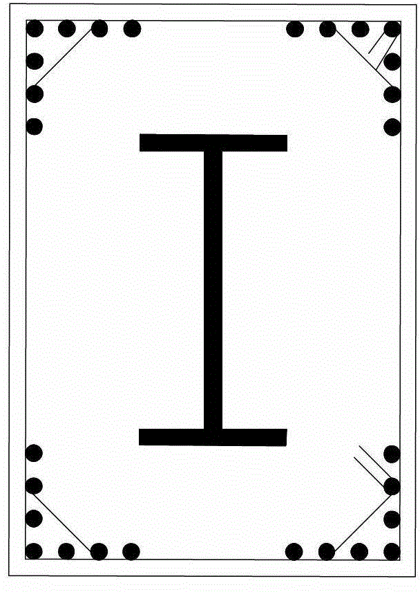
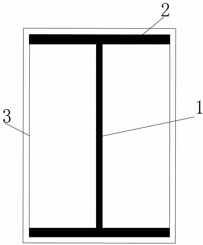
[0039] The shaped steel column 1 is made by a professional steel structure company. The width of the shaped steel flange 2 is equal to the width of the column minus 70mm. When processing the shaped steel flange and web, round holes are set on it. The rectangular spiral hoop is processed by the CNC hoop bending machine with a machining accuracy of ±1mm. The manufactured rectangular spiral hoop 3 is placed on the section steel, and the inner surface of the spiral hoop constraining the section steel flange 2 should be attached to the outer surface of the section steel flange. A section of shaped steel column corresponds to several circles of spiral hoops. The initial end of the spiral hoop must surround the shaped steel for one circle, and the end of the spiral hoop must surround the shaped steel for one circle. Less than 10d, the strength of the electrode is not less than 500 MPa, and the weld must be full.


PUM

PropertyMeasurementUnit
thicknessaaaaaaaaaa
yield strengthaaaaaaaaaa

Abstract

The invention provides an H-shaped steel concrete column with a high-strength spiral hoop and a restraining high-strength wide flange and relates to a sectional steel concrete column. The defects of the present I-shaped and H-shaped steel concrete columns that the construction is difficult, the anti-bending function of the sectional steel is not completely utilized because a concrete protecting layer is thick, and the high-strength sectional steel is easy to press and deflect are overcome. A longitudinal reinforcement is abolished, a steel area is converted into the sectional steel flange and the construction and the design of the sectional steel concrete column are convenient to perform. The spiral hoop is a high-strength rectangular spiral hoop; the inner side of the spiral hoop of the restraining sectional steel flange is clung to the surface of the sectional steel flange; and an unstable critical stress of the sectional steel flange is increased by a free edge of the restraining sectional steel flange; the spiral hoop is tightly combined with the flange, so that a function of a bolt is achieved and the concrete can more effectively coordinate with the sectional steel; the concrete protecting layer of the sectional steel is 30-40mm thick, thereby being fireproof requirement and fully utilizing the anti-bending function of the sectional steel; a screw pitch of the rectangular spiral hoop is 0-60mm, so that the restraining condition of the free edge of the restraining sectional steel flange is obviously improved; and the H-shaped steel concrete column provided by the invention is applied to a sectional steel concrete structure.

Description

technical field [0001] The invention relates to a steel concrete column. Background technique [0002] Shaped steel concrete column refers to the structure that configures shaped steel in concrete, and is equipped with certain transverse stirrups and longitudinal reinforcement bars. The medium-sized steel in the column mainly includes I-shaped steel, H-shaped steel and cross-shaped steel. Steel concrete columns have the advantages of high bearing capacity, high rigidity and good seismic performance, and have been widely used in long-span structures and high-rise buildings in earthquake zones. [0003] In steel-concrete columns, two materials with different properties, steel and concrete, can work together because of the bonding effect between them. Since the surface of the steel is smooth, the bond strength between the steel and concrete is equivalent to that of a smooth round steel bar and concrete. 60% of the threaded steel bar and 30% of the bond strength of concrete. In...

Claims


Application Information

Patent Timeline
Patent Type & Authority Applications(China)
IPC IPC(8): E04C3/34
Inventor 管俊峰白卫峰张建伟张翌娜姚贤华
Owner NORTH CHINA UNIV OF WATER RESOURCES & ELECTRIC POWER
Learn More