Plate-shaped heat exchange element as well as hydrophilous heat exchange device and manufacturing method of plate-shaped heat exchange element

A heat exchange element, plate-shaped technology, applied in heat exchange equipment, laminated elements, fixed plate conduit components, etc., can solve the problems of limited heat exchange area, complicated manufacturing process, high operating cost, etc., and achieves easy installation and maintenance. Increase heat exchange area, anti-fouling, easy to clean and maintain

Inactive Publication Date: 2012-10-24
上海吉益能源技术有限公司
View PDF5 Cites 14 Cited by
  • Summary
  • Abstract
  • Description
  • Claims
  • Application Information

AI Technical Summary

Problems solved by technology

The heat exchanger is filled with refrigerant and condensing oil as the heat transfer medium. On the one hand, its operating cost is high, and the heat transfer area is limited by the amount of refrigerant injected, which cannot meet the low temperature and large requirements of the outdoor surface water heat exchange device for the closed surface wate

Method used


Image

  • Plate-shaped heat exchange element as well as hydrophilous heat exchange device and manufacturing method of plate-shaped heat exchange element
  • Plate-shaped heat exchange element as well as hydrophilous heat exchange device and manufacturing method of plate-shaped heat exchange element
  • Plate-shaped heat exchange element as well as hydrophilous heat exchange device and manufacturing method of plate-shaped heat exchange element

Examples


Embodiment Construction

[0037] In order to better understand the above technical solutions of the present invention, a further detailed description will be given below in conjunction with the drawings and embodiments.

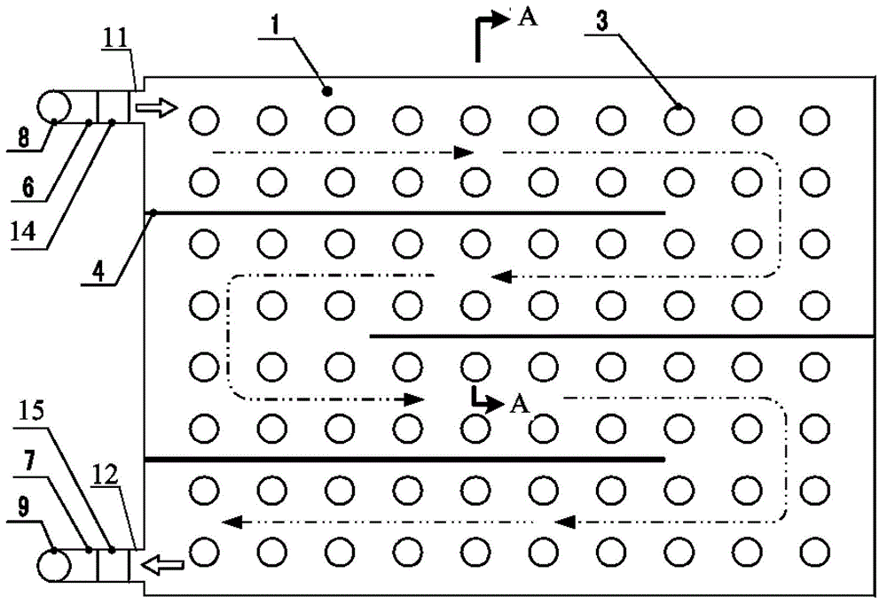
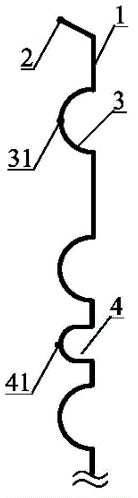
[0038] The structure of the plate heat exchange element 10 of the water medium heat exchange device used in the surface water source heat pump system of the present invention is as follows: figure 1As shown, it includes a water inlet 11, a water outlet 12 and two heat exchange plates 1 and 1' welded on the periphery. Between the two heat exchange plates 1 and 1', there is a water inlet 11 and a water outlet. 12 connected circulation chambers, the heat exchange plates 1 and 1' are provided with a stamped and stretched diversion belt structure 4 and an enhanced heat exchange structure 3; the diversion belt structure 4 has a U-shaped cross-sectional shape on the heat exchange plate Or V-shaped strip-shaped protrusions. exist figure 1 in, in figure 2 The cross-sectional shape of the m...


PUM


Abstract

The invention discloses a plate-shaped heat exchange element as well as the hydrophilous heat exchange device and the manufacturing method of the plate-shaped heat exchange element and relates to a plate-shaped heat exchange or heat transfer element which has a structure that heat transfer area is increased and is especially applicable to a heat exchange device of a closed surface water source heat pump system. The plate-shaped heat exchange element comprises a water inlet, a water outlet and heat exchange plates, wherein each heat exchange plate is used for welding the combined peripheral edges; the plate-shaped heat exchange element is provided with a circulating cavity body communicated with the water inlet and the water outlet; the heat exchange plates are provided with guide flow belt structures and enhanced heat exchange structures which are formed by stamping and drawing; the circulating cavity body is divided into an S-shaped heating medium water channel; the enhanced heat exchange structures form a supporting structure between the heat exchange plates. The plate-shaped heat exchange element has the advantages that a heat exchange flow channel is reasonable in design, short in process and low in water resistance, so that the power consumption of a circulating water pump at the surface water source side of the closed surface water source heat pump system can be obviously saved; high-pressure expansion is replaced by using stamping forming and peripheral-edge welding, the manufacturing process is simplified, the problems of rough deformation and easy scaling on the local surfaces of the heat exchange plates due to high-temperature welding are solved, and due to the same-mold heat exchange plates, the manufacturing cost of a stamping mold can be reduced.

Description

technical field [0001] The invention relates to a plate-shaped heat exchange or heat transfer element and its assembly with a structure to increase the heat transfer area, and is especially suitable for a heat exchange device of a closed surface water source heat pump system. Background technique [0002] Ground source heat pump is a new type of air-conditioning technology that uses shallow ground energy for heating and cooling, which is highly efficient, energy-saving and environmentally friendly. The ground source heat pump utilizes the huge heat storage and cold storage capacity of the underground soil, through the pipeline system buried deep around the building or under the floor, adopts the heat pump principle, and realizes the transfer of low-level heat energy to high-level heat energy through a small amount of high-level electric energy input, making the underground A technology for heat exchange between rock and soil mass and buildings. The closed surface water sour...

Claims


Application Information

Patent Timeline
IPC IPC(8): F28F3/04F28D9/00F25B30/06B23P15/26
Inventor 王宽雷刚成剑林雷波
Owner 上海吉益能源技术有限公司
Why Eureka
Try Eureka