
Device and method for detecting cable oscillatory wave partial discharge and fault location

A technology for partial discharge detection and fault location, applied in the direction of testing dielectric strength, etc., can solve problems such as bulky equipment, prolonged measurement time, and cable damage

Inactive Publication Date: 2012-10-24
西安博源电气有限公司
View PDF6 Cites 42 Cited by
  • Summary
  • Abstract
  • Description
  • Claims
  • Application Information

AI Technical Summary

Problems solved by technology

These methods can detect the partial discharge of cables, but there are certain problems at the same time. 1. The cable partial discharge detection equipment under power frequency voltage is bulky and heavy, and it is not easy to detect cable partial discharge on site; 2. Detection under ultra-low frequency voltage The reliability of partial discharge results is not high, and prolonged measurement time may cause damage to the cable; 3. Cable partial discharge detection under DC damped oscillating wave voltage, using DC to charge the cable, may leave residual charges after the test. Cables Bring Insecurity
At present, there are certain problems in several methods of offline detection of cables, which need to be solved urgently

Method used


Image

  • Device and method for detecting cable oscillatory wave partial discharge and fault location
  • Device and method for detecting cable oscillatory wave partial discharge and fault location
  • Device and method for detecting cable oscillatory wave partial discharge and fault location

Examples


Embodiment Construction

[0019] The structural principle and working principle of the present invention will be described in detail below in conjunction with the accompanying drawings.

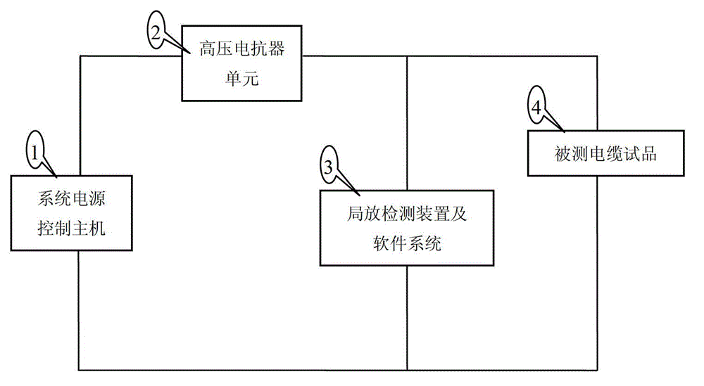
[0020] refer to figure 1 , the detection device for cable oscillatory partial discharge and fault location, including system power control host 1, high voltage reactor unit 2, partial discharge detection device and software system 3, tested cable test product 4, system power control host 1 voltage output terminal It is connected to the input terminal of the high voltage reactor unit 2, and the ground terminal of the system power control host 1 is connected to the ground terminal of the partial discharge detection device and the software system 3, and the shielding layer terminal of the tested cable test object 4; the ground terminal of the high voltage reactor unit 2 The output terminal is connected to the input terminal of the partial discharge detection device and software system 3, and is connected to the 4-wire c...


PUM


Abstract

The invention discloses a device and a method for detecting cable oscillatory wave partial discharge and fault location, wherein the device comprises a system power supply control host, a high voltage reactor unit, a partial discharge detection device, a software system and a cable sample to be tested, 220V alternating voltage is input into the system power supply control host, and is converted into direct voltage through a rectifier, and the direct voltage is converted into the alternating voltage with adjustable frequency and amplitude through an inverter. The system power supply control host automatically searches the system resonant frequency, the output voltage is adjusted to reach the initial set test voltage value of the system, users carry out cable withstand voltage tests or damped oscillation wave partial discharge detection tests according to the requirements, and the system locates the fault location through analysis and diagnosis according to the acquired cable partial discharge signals.

Description

technical field [0001] The invention belongs to the field of power cable insulation detection, and in particular relates to a detection device and method for XLPE (cross-linked polyethylene) cable oscillation wave partial discharge and fault location under damped oscillation wave voltage based on frequency conversion resonance. Background technique [0002] In the past ten years, a large number of XLPE power cables have been used in my country's urban power grids for power transmission and distribution. Cross-linked cables play a vital role in the current power system in China and the world, and have become the leading product for power transmission in cities. Because the insulation structure of this XLPE cable is difficult in processing technology or the raw materials are impure, there are air gaps and harmful impurities, or there is a gap between the insulation and the semi-conductive shielding layer due to process reasons, or the semi-conductor protrudes toward the insula...

Claims


Application Information

Patent Timeline
IPC IPC(8): G01R31/12
Inventor 张有平李高峰王长安
Owner 西安博源电气有限公司
Learn More