Movable contact member and switchgear using the same

A technology for moving contacts and components, applied in the field of movable contact components and switch devices, can solve the problems of inability to achieve miniaturization of switch devices, insufficient travel, and reduced switch life, and achieve extended life, long travel, and restraint. crack effect

Active Publication Date: 2015-10-28
ALPS ALPINE CO LTD
View PDF9 Cites 0 Cited by
  • Summary
  • Abstract
  • Description
  • Claims
  • Application Information

AI Technical Summary

Problems solved by technology

[0007] However, if Figure 9 Like the movable contact member 911 of Conventional Example 2 shown, when the leg portion 905 is lengthened, the stress concentrates on the curved portion between the dome-shaped spring portion 904 and the leg portion 905, and the number of repetitions increases. 100,000 times of overturning causes cracks to occur at the boundary portion 909 between the spring portion 904 and the leg portion 905, and there is a problem that the life of the switch is reduced.
On the other hand, in order to prolong switch life, such as Figure 8 The leg 812 is shortened like the contact spring 811 of the conventional example 1 shown in (a), or Figure 8 The contact spring 844 of the conventional example shown in (b) may be configured without a leg, but as described above, there is a problem that a sufficient stroke cannot be obtained.
In addition, in a switchgear generally manufactured in a square shape, in order to lengthen the stroke, such as Figure 9 In the case of the contact spring having the shape of the movable contact member 911 of the conventional example 2 shown, the maximum external shape including the legs is larger than the maximum external shape of the dome, and there is a problem that the switch device cannot be miniaturized. this kind of subject

Method used


Image

  • Movable contact member and switchgear using the same
  • Movable contact member and switchgear using the same
  • Movable contact member and switchgear using the same

Examples


no. 1 approach

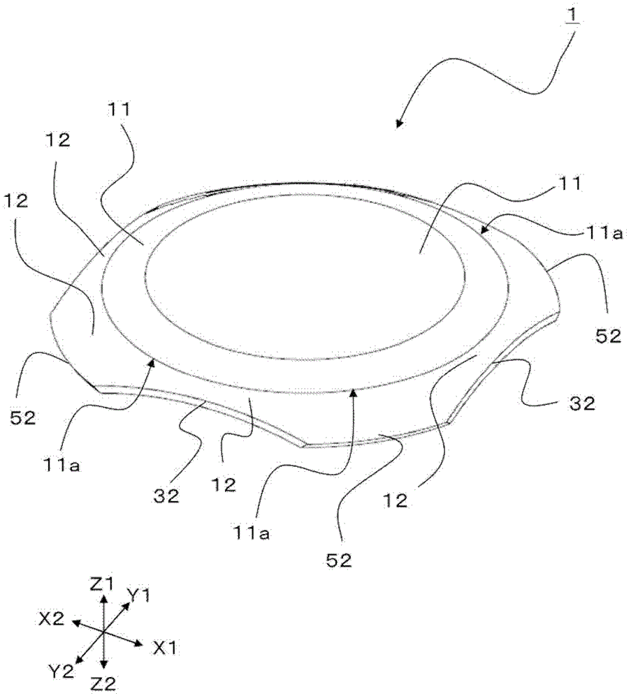
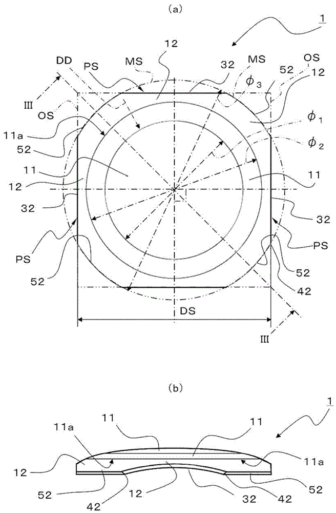
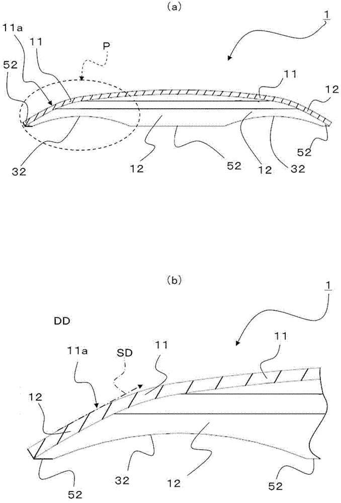
[0046] figure 1 It is a perspective view explaining the movable contact member 1 of the first embodiment of the present invention. figure 2 It is a figure explaining the movable contact member 1 of 1st Embodiment of this invention, figure 2 (a) is a plan view, figure 2 (b) is a side view. image 3 It is a figure explaining the movable contact member 1 of 1st Embodiment of this invention, image 3 (a) is figure 2 (a) The cross-sectional view of line III-III shown in (a), image 3 (b) is image 3 (a) An enlarged cross-sectional view of part P shown in (a).

[0047] like figure 1 As shown, the movable contact member 1 is configured to include: a bulging portion 11 formed of a conductive metal plate, which can be reversed by pressing; formed continuously. Thereby, since the skirt part 12 is formed continuously with the outer peripheral edge part 11a of the bulging part 11, it becomes the structure which supports the bulging part 11. As shown in FIG.

[0048] like ...

no. 2 approach

[0063] Figure 4 It is a perspective view explaining the switch device 201 of 2nd Embodiment of this invention. Figure 5 It is an exploded perspective view illustrating the switch device 201 according to the second embodiment of the present invention. Image 6 is a diagram illustrating a switch device 201 according to a second embodiment of the present invention, Image 6 (a) is a top view of the switch base 4, Image 6 (b) is a plan view in which the movable contact member 1 is placed on the switch base 4 . In addition, the same code|symbol is attached|subjected to the same structure as 1st Embodiment, and detailed description is abbreviate|omitted.

[0064] like Figure 4 to Figure 6 As shown, the switch device 201 according to the second embodiment of the present invention is configured to include: the movable contact member 1 according to the first embodiment of the present invention; the switch base 4 having a housing portion 14 for receiving the movable contact member...

Deformed example 1

[0074] In the above-described embodiment, the grounding portion of the contact portion 52 of the movable contact member 1 is configured to be linearly inclined, but it may be as follows: Figure 7 As shown in (a), the ground portion of the contact portion C62 is bent. Therefore, it is possible to reduce the wear of the peripheral fixed contacts 5 and the contact portion C62 caused by the repeated inversion operation of the movable contact member C11. Thereby, the lifetime of a switch device can be extended further.


PUM


Abstract

A movable contact member (1) includes a swelling portion (11) that swells in the shape of a dome and can operates reverselywhen pressed, and a skirt portion (12) that is continuously formed from an outer peripheral edge portion (11a) of the swelling portion (11). The skirt portion (12) includes cut-out portions (32) cut out at four portions thereof, portions of the skirt portion (12) except for the cut-out portions (32) form contact portions (52), the cut-out portions (32) of the skirt portion (12) swell toward the swelling portion (11) so that portions of the skirt portion (12) except for the cut-out portions (32) form portions capable of being grounded, and a cut-out face shape (PS) of each of the cut-out portions (32) is a linear shape or a gently curved shape when the skirt portion (12) does not swell. Further, a switch device (201) is formed using the movable contact member (1).

Description

technical field [0001] The present invention relates to a movable contact member and a switch device using the movable contact member, and more particularly to a movable contact in which the movable contact member performs an inverting operation when the movable contact member is pressed to separate contacts. Components and switchgear using the movable contact components. Background technique [0002] In general, as movable contact parts used in electronic devices such as digital cameras and mobile phones, in order to obtain operational feeling such as operating force and click feeling, the movable contact parts are used to make contact by being pressed and flipped. The contact separation of the movable contact part. As such a movable contact member, a dome-shaped movable contact member formed by processing a thin metal plate with a predetermined curvature is known. [0003] As prior art, it is proposed in Patent Document 1 as Figure 8 (a) A contact spring 811 provided wi...

Claims


Application Information

Patent Timeline
Patent Type & Authority Patents(China)
IPC IPC(8): H01H1/24H01H13/12
CPCH01H13/79H01H5/30H01H13/48H01H13/705H01H2203/05H01H2209/012H01H2215/036H01H2227/026H01H2227/028H01H2227/036
Inventor 贞松伊鹤高桥一成田泽俊彦
Owner ALPS ALPINE CO LTD
Why Eureka
Try Eureka