High-capacity reversible charging and discharging device

A charge-discharge device and large-capacity technology, applied in circuit devices, battery circuit devices, collectors, etc., can solve the problems of discharge energy waste, loss, and small ships that are not prominent

Active Publication Date: 2012-10-24
浙江欣展科技有限公司
View PDF9 Cites 16 Cited by
  • Summary
  • Abstract
  • Description
  • Claims
  • Application Information

AI Technical Summary

Problems solved by technology

[0003] 1. The charging and discharging device of the ship battery generally uses a DC switching power supply as the charging device, and a resistive load as the discharging device. The discharge energy is not recycled and is wasted. This contradiction is not prominent on small ships, but it will be on medium and large ships. non-negligible loss
[0004] 2. The charging method and maintenance of the ship's battery charging and discharging device are also limited to the conventional modes of constant current, constant voltage, floating charge, fast charging and discharging, and the charging and discharging and maintenance of the battery cannot be in its own optimal working state
[0005] 3. The charging and discharging device of the ship’s battery has not monitored the capacity of the battery so far, and the detection of the capacity of the battery will most effectively reflect the performance and operation of the battery, and it is also an important data for the combat readiness of the ship. Therefore, the above key parameters to detect

Method used


Image

  • High-capacity reversible charging and discharging device
  • High-capacity reversible charging and discharging device
  • High-capacity reversible charging and discharging device

Examples


Embodiment 1

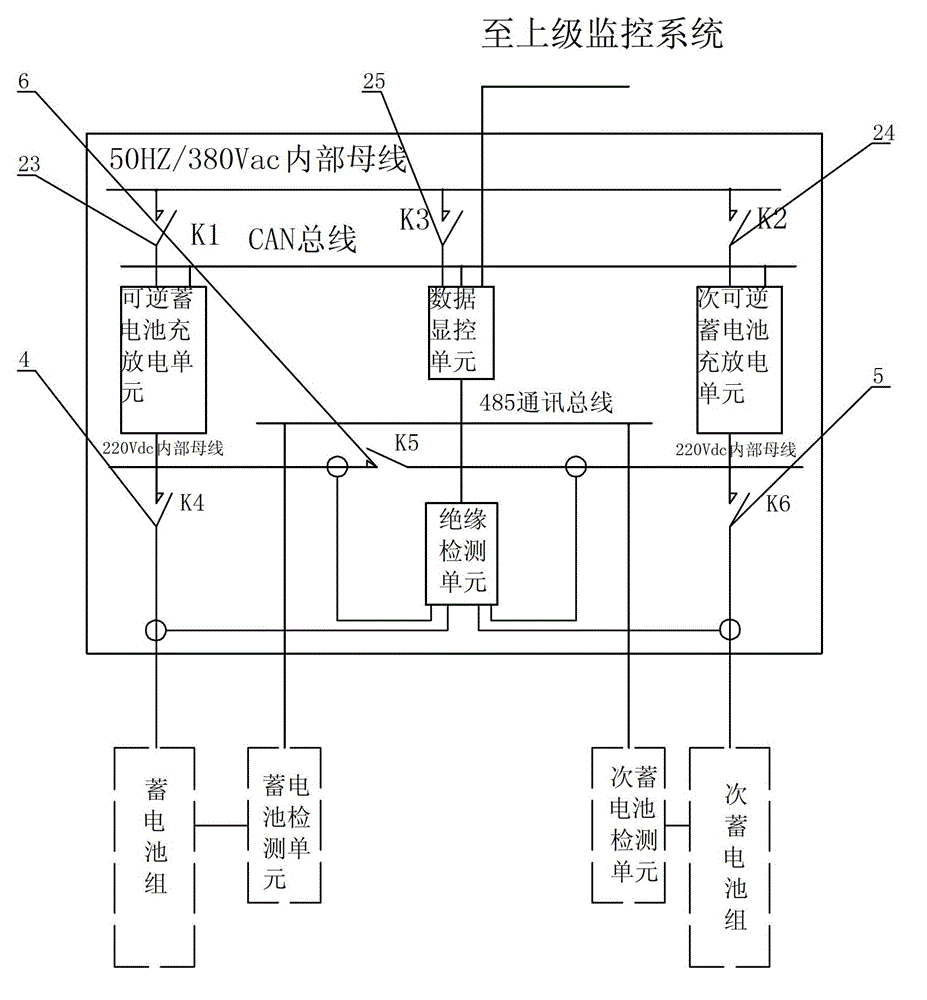
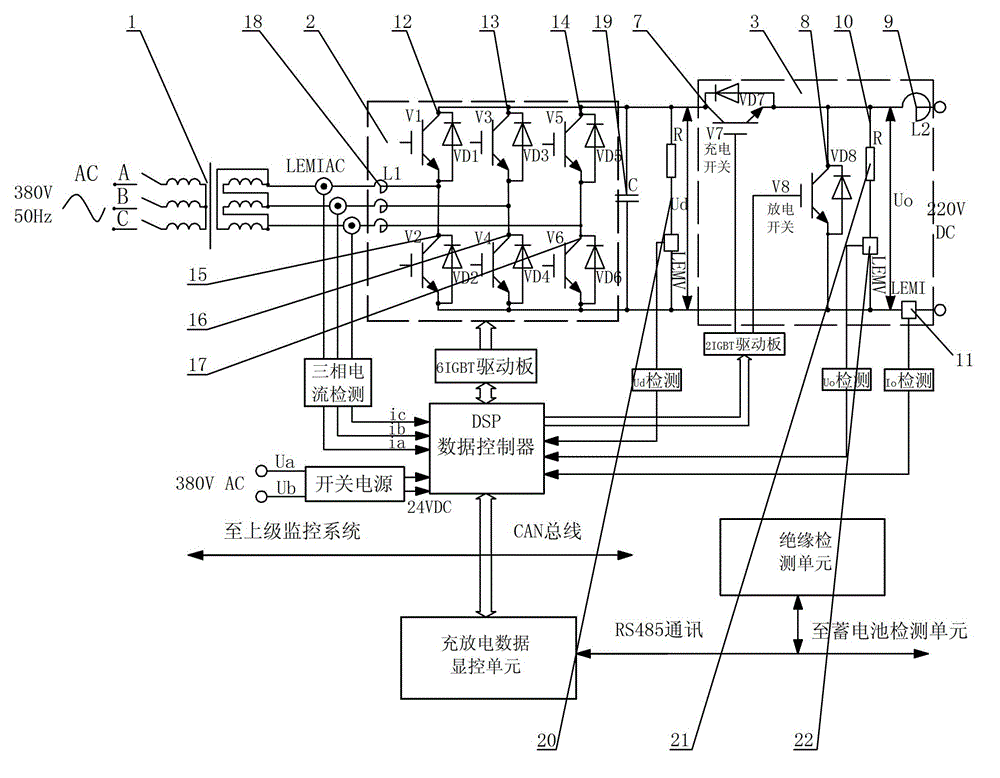
[0033] see figure 1 , the device is a large-capacity reversible charge and discharge device, including a reversible storage charge and discharge unit, a data display and control unit, an insulation detection unit, a storage battery pack, a storage battery detection unit, and a host computer. The reversible storage charge and discharge unit includes a transformer 1, SVPWM reversible three-phase rectification and inverter bridge 2, DSP data controller, and bidirectional DC / DC conversion module 3 for charging and discharging mode conversion. There is a switch K between the busbars of the high-voltage system 1 23. The output end of the reversible storage charging and discharging unit is connected to the battery pack, and at the same time, it is also equipped with a secondary reversible storage charging and discharging unit, a secondary storage battery pack and a secondary storage battery detection unit, a secondary reversible storage charging and discharging unit, a secondary stor...


PUM


Abstract

The invention provides a high-capacity reversible charging and discharging device which is characterized by comprising a reversible electric power storage and charge-discharge unit, a data display control unit, an insulation detection unit, a storage battery, a storage battery detection unit and an upper computer, wherein the reversible electric power storage and charge-discharge unit sequentially comprises a transformer, a space vector pulse width modulation (SVPWM) reversible three-phase rectifier inverter bridge, a digital signal processor (DSP) data controller and a two-way DC (direct current)/ DC conversion module used for converting charging and discharging modes; the reversible electric power storage and charge-discharge unit is led out from a high-voltage system bus; an output end of the reversible electric power storage and charge-discharge unit is connected with the storage battery; the data display control unit is respectively connected with the reversible electric power storage and charge-discharge unit, the insulation detection unit and the storage battery detection unit; the storage battery detection unit is connected with the storage battery by data; and the insulation detection unit is connected with an output end of the reversible electric power storage and charge-discharge unit. The reversible electric power storage and charge-discharge unit is added into the device, so that the device integrates reversible charging and discharging; therefore, the device can be used for rectifying charging and discharge inversion to realize grid-connected operation with the main power grid.

Description

technical field [0001] The invention relates to a battery charging and discharging device, in particular to a large-capacity reversible charging and discharging device. Background technique [0002] At present, the battery charging device of our country's ships is gradually replaced by the traditional unit type DC power supply, and is gradually replaced by the DC switching power supply of power electronics. With the improvement of the automation level of national defense equipment, the ship battery charging device has also made great progress. The status quo of the charging and discharging device of the ship battery is as follows: [0003] 1. The charging and discharging device of the ship battery generally uses a DC switching power supply as the charging device, and a resistive load as the discharging device. The discharge energy is not recycled and is wasted. This contradiction is not prominent on small ships, but it will be on medium and large ships. A loss that cannot ...

Claims


Application Information

Patent Timeline
Patent Type & Authority Applications(China)
IPC IPC(8): H02J7/04H02J3/38
Inventor 洪玮何通能
Owner 浙江欣展科技有限公司
Why Eureka
Try Eureka