Aerodynamic coefficient estimation device and control surface failure/damage detection device

An aerodynamic coefficient and damage detection technology, applied in aerodynamic tests, aircraft health monitoring devices, measuring devices, etc., can solve problems such as increased weight of the fuselage, inability to detect faults, false detections, etc., and achieve the effect of reducing the burden

Inactive Publication Date: 2012-10-24
MITSUBISHI HEAVY IND LTD
View PDF3 Cites 5 Cited by
  • Summary
  • Abstract
  • Description
  • Claims
  • Application Information

AI Technical Summary

Problems solved by technology

[0006] However, in the case of estimating the aerodynamic coefficient using the above-mentioned successive least squares method, there is a problem that an angular acceleration is required in order to calculate the aerodynamic coefficient, so it is necessary to mount a sensor for detecting the angular acceleration on the aircraft. When resetting the sensor, there is a problem of increasing the weight of the fuselage
In addition, there is a problem that it may not be possible to obtain an accurate estimated value of the aerodynamic coefficient by only relying on one method such as the successive least square method or the neural network method to estimate the aerodynamic coefficient.
Therefore, when the aerodynamic coefficient obtained by the successive least square method or the neural network method is applied to the fault and damage detection of the control surface, there is a possibility that false detection may occur, and the detection result cannot be reflected in the flight control rules without preparation. question
In addition, the method of laying optical fibers etc. on the fuselage has the problem that failure detection cannot be performed in the event of failure or damage.

Method used


Image

  • Aerodynamic coefficient estimation device and control surface failure/damage detection device
  • Aerodynamic coefficient estimation device and control surface failure/damage detection device
  • Aerodynamic coefficient estimation device and control surface failure/damage detection device

Examples


no. 1 approach )

[0051] Next, an aerodynamic coefficient estimation device according to a first embodiment of the present invention will be described with reference to the drawings.

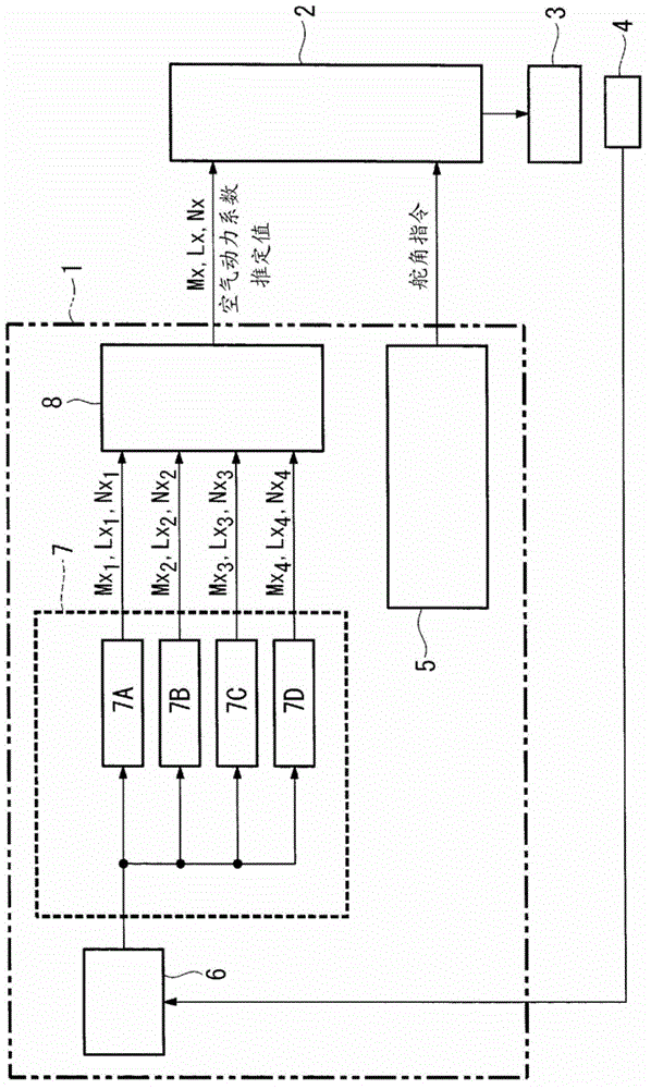
[0052] figure 1 It is a block diagram showing a schematic configuration of the aerodynamic coefficient estimating device according to the first embodiment. The aerodynamic coefficient estimating device 1 estimates an aerodynamic coefficient representing the aerodynamic characteristics of the aircraft, such as figure 1 As shown, an aerodynamic coefficient estimating device 1, a flight control system 2 suitable for an aircraft and controlling the fuselage of the aircraft, a control surface 3 for generating aerodynamic force for controlling the attitude of the fuselage, and a sensor for detecting the motion state of the fuselage 4 connections.

[0053] The flight control system 2 is a system for controlling the entire aircraft, and constitutes flight control rules based on the airframe and flight states, and furth...

no. 2 approach )

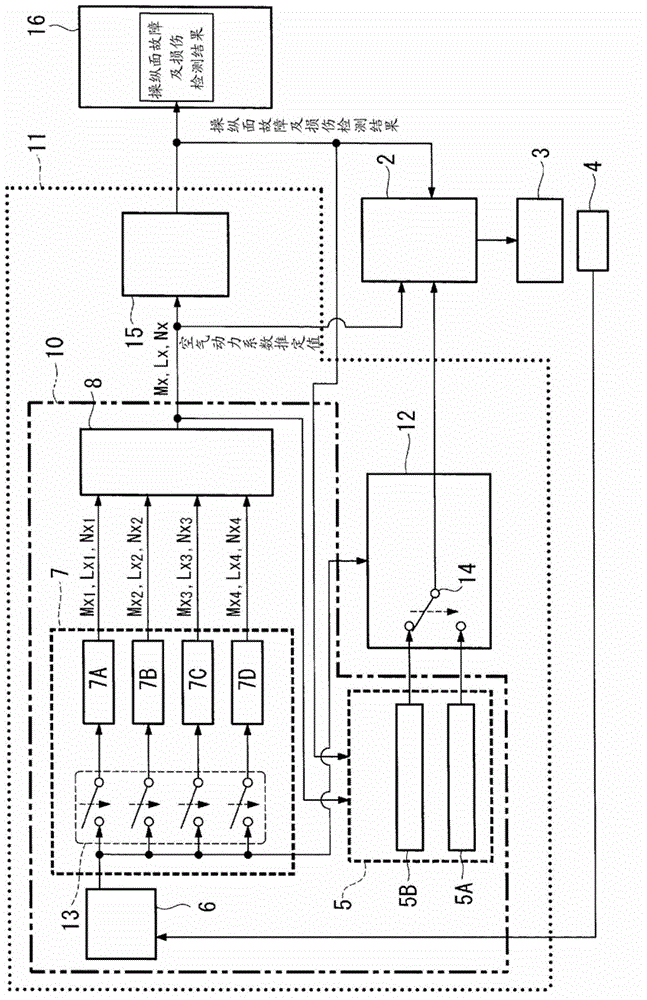
[0068] Next, a control surface failure and damage detection device according to a second embodiment of the present invention will be described with reference to the drawings.


PUM


Abstract

The disclosed device can compute a high-reliability estimate of aerodynamic coefficients, allowing accurate detection of failure of or damage to control surfaces while reducing the burden on passengers. Said device is provided with: a control-angle command-signal generation means (5) that generates a control-angle command signal for estimating aerodynamic coefficients that indicate the aerodynamic characteristics of an airframe; a kinetic state quantity acquisition means (6) that acquires kinetic state quantities for the airframe, resulting from control surfaces provided on the airframe being driven on the basis of the control-angle command signal; a candidate-value computation means (7) that uses at least two different estimation methods to compute, from the kinetic state quantities, candidate values for estimating the aforementioned aerodynamic coefficients; and an aerodynamic coefficient estimate determination means (8) that determines aerodynamic coefficient estimates on the basis of the candidate values.

Description

technical field [0001] The present invention relates to an aerodynamic coefficient estimating device and a control surface failure and damage detection device using the same, and more particularly to an aerodynamic coefficient estimating device for estimating an aerodynamic coefficient representing the aerodynamic characteristics of an aircraft, and to detecting an aircraft using the estimated aerodynamic coefficient Control surface failure and damage detection device for control surface failure and damage. Background technique [0002] When estimating the aerodynamic coefficient representing the aerodynamic characteristics of an aircraft, a method is known in which the angle of attack, side slip angle, airspeed, angular velocity, attitude angle, rudder angle, etc. are obtained from various sensors installed in the aircraft. Information, based on these information, the operation of successive least square method and neural network method is carried out. There is also known ...

Claims


Application Information

Patent Timeline
Patent Type & Authority Applications(China)
IPC IPC(8): B64C13/00G01M9/06
CPCG05D1/0077G08G5/0021B64C13/00G08G5/0013G01M9/08G01M9/06G01C23/005B64D2045/0085G01C23/00
Inventor 山崎光一
Owner MITSUBISHI HEAVY IND LTD
Why Eureka
Try Eureka