Non-aqueous cell having a mixture of fluorinated carbon cathode materials

A cathode material, chemical battery technology, applied to battery electrodes, circuits, electrical components, etc., can solve problems such as low working voltage power capacity

Active Publication Date: 2012-10-24
EAGLE PICHER TECH LLC
View PDF15 Cites 30 Cited by
  • Summary
  • Abstract
  • Description
  • Claims
  • Application Information

AI Technical Summary

Problems solved by technology

However, despite the high energy density and good stability of the cells, the Li / CF cathode cells have not been used for high rate applications due to the high resistivity of the cathode matrix resulting in low operating voltage and limited power capacity (as can be implanted cardiac defibrillator (or ICD)

Method used


Image

  • Non-aqueous cell having a mixture of fluorinated carbon cathode materials
  • Non-aqueous cell having a mixture of fluorinated carbon cathode materials
  • Non-aqueous cell having a mixture of fluorinated carbon cathode materials

Examples


Embodiment 1

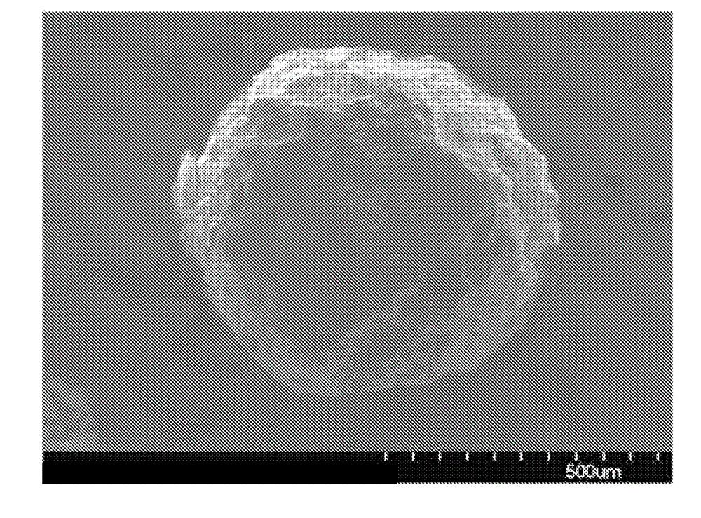
[0087] Example 1: Fluorinated carbons (CF 1 ) and fluorocarbons (CF 1 ) physical and chemical characterization

[0088] Determination of fluorinated carbons (i.e., CF x , which can be used as CF 1 Commercially available, but as given in Table 2 below, it was determined analytically to be closer to CF 0.9 ) and fluorocarbons derived from pitch (ie, CF z , as given in Table 2 below, which in this case is CF 1 ) X-ray diffraction pattern to characterize the properties and physical structure of the CF material ( image 3 ). image 3 This shows that there is very little difference in the XRD signals between these two CF materials.

[0089] The crystal size of the material is calculated by the following formula:

[0090]

[0091] Among them, L c is the crystal size, K is the instrument constant (usually 1), λ is the wavelength of X-rays (1.54 Å), L is the full width at half maximum (FWHM), and θ is the diffraction angle. The crystal size (L c ) is 2.99 nm, wh...

Embodiment 2

[0102] Example 2: Determination of the discharge curve (50J pulse) of a prior art battery and a battery containing a hybrid cathode according to the invention

[0103] Two 2.5Ah Li / CF cells were constructed in sealed aluminum bags. One cell contains a hybrid cathode containing a mixture of three CF materials: 40% by weight of the formula CF 1 of fluorinated carbons derived from coke, 10% by weight of formula CF 0.6 of fluorocarbons derived from coke and 50% by weight of formula CF 1 of fluorocarbons derived from bitumen. The second battery is a prior art Li / CF battery. The hybrid cathode also contains carbon as conductive filler (6% by weight of KS-4 graphite for the cathode and 4% by weight of Super P carbon black for the cathode, both from TIMCAL) and Polyvinylidene fluoride (PVDF). The materials were mixed and spread on a carbon coated aluminum current collector. About five pairs of cathode separators and anodes are stacked and formed into the bag cell.

[0104] Th...

Embodiment 3

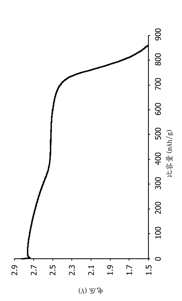
[0107] Example 3: Determination of the discharge curve (50J pulse) of a battery containing a carbon fluoride cathode derived from pitch

[0108] For the purpose of comparison with Example 2, a fluorinated carbon cathode (CF) derived from pitch was prepared according to the method of Example 2 1 or P5000) batteries. The battery was subjected to the same 50J pulse process as in Example 2 ( Figure 13 ). Such as Figure 13 As shown, the minimum voltage of the pulse at the beginning of life is about 2.5V high. Figure 13 Also shown is the curve for a battery containing the hybrid battery of Example 2, which has a minimum voltage of 2.4 V high.


PUM

PropertyMeasurementUnit
particle sizeaaaaaaaaaa

Abstract

The present disclosure relates generally to a cathode material suitable for use in a non-aqueous electrochemical cell that comprises a mixture of fluorinated carbon materials, and more particularly such a cell that comprises a mixture of three fluorinated carbon materials that each have distinct (from each other) discharge profiles (e.g., distinct voltages and capacities). The present disclosure additionally relates to a non-aqueous electrochemical cell comprising such cathode material and, in particular, to such a non-aqueous electrochemical cell that is lithium-based (i.e., a lithium, or lithium ion, non-aqueous electrochemical cell).

Description

[0001] Cross References to Related Applications [0002] This application claims the benefit of US Provisional Application No. 61 / 266,628, filed December 4, 2009, which is hereby incorporated by reference in its entirety. field of invention [0003] The present invention relates generally to cathode materials suitable for use in non-aqueous electrochemical cells comprising a mixture of fluorinated carbon materials, and more particularly to such cells comprising three fluorinated carbons A mixture of materials, each of the fluorocarbon materials having a different discharge profile (eg, different voltage and capacity) than one another. In addition, the present invention relates to non-aqueous electrochemical cells comprising such cathode materials, and in particular to such non-aqueous electrochemical cells that are lithium-based (ie, lithium or lithium-ion non-aqueous electrochemical cells). Background of the invention [0004] Lithium electrochemical cells, more commonly k...

Claims


Application Information

Patent Timeline
Patent Type & Authority Applications(China)
IPC IPC(8): H01M4/133
CPCH01M4/1393Y02E60/122H01M4/133H01M4/587Y02E60/10
Inventor D.张M.德斯蒂芬V.武J.C-H.常H.J.邦
Owner EAGLE PICHER TECH LLC
Why Eureka
Try Eureka