Gas explosion-preventive spiral spray pipe bubbling stirring apparatus

A stirring device and spiral spray technology, which is applied in the field of bubbling and stirring in the batching tank, can solve the problems of dead angle of stirring, easy flushing out of the liquid surface, complex structure, etc., and achieve the effect of easy maintenance, easy installation and simple operation

Inactive Publication Date: 2014-04-09
UNIV OF JINAN
View PDF5 Cites 1 Cited by
  • Summary
  • Abstract
  • Description
  • Claims
  • Application Information

AI Technical Summary

Problems solved by technology

However, in the existing bubbling and stirring device for the batching tank, the compressed air from the air compressor enters the batching tank from the cone bottom of the batching tank, and the direction of the compressed air flow is vertically upward. Boiling and rushing out of the batching tank will cause gas explosion, and most of the compressed air is not involved in stirring and is wasted. The power consumption is large, the stirring efficiency is low, and the air flow is small. The solid phase deposited at the bottom is difficult to be stirred by the air flow, forming a dead angle of stirring. long time
The bubbling and stirring device of the prior art Chinese patent CN201887067U discloses a bubbling and stirring type cashmere tank rehydration device, but its structure is complicated, and the bubbling form of the air outlet on the square tube is adopted, and the air flow passes through the vertical and horizontal direction of the square tube. The air outlet realizes the stirring of the materials in the reaction tank. This kind of stirring device has disadvantages. One is the vertically upward air outlet. The initial velocity direction is vertically upward, and the floating speed of the bubbles is also vertically upward. The upward speed direction of the two-speed synthesis quickly breaks away from the reaction interface, resulting in high power consumption and low stirring efficiency; the second is that the bottom of the reactor is easy to form a stirring dead angle; the third is multiple bubbling stirring parts placed at the bottom, and the structure is complex and easy to block , not conducive to cleaning
The Chinese patent with the application number 200910252129.0 has a simple structure and is easy to clean and maintain. However, there are also dead spots in the bottom of the reactor and the direction of the initial velocity is vertically upward. The floating speed of the bubbles is also vertically upward. The upward speed direction quickly breaks away from the reaction interface, the defects of large power consumption and low stirring efficiency

Method used


Image

  • Gas explosion-preventive spiral spray pipe bubbling stirring apparatus
  • Gas explosion-preventive spiral spray pipe bubbling stirring apparatus
  • Gas explosion-preventive spiral spray pipe bubbling stirring apparatus

Examples


Embodiment 1

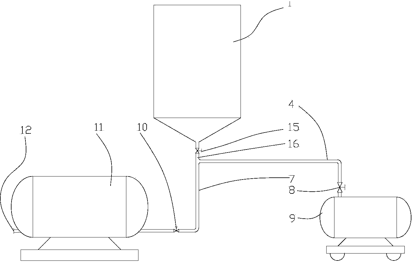
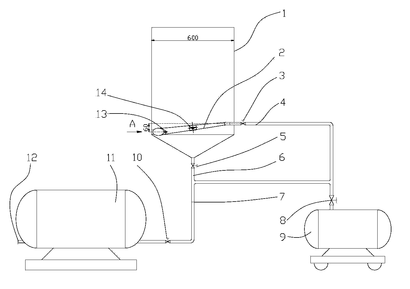
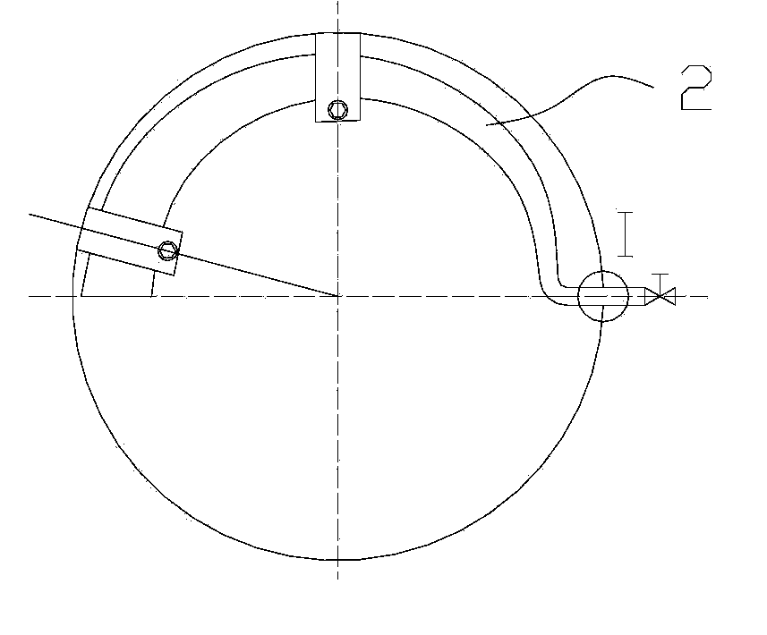
[0022] The present invention comprises: a batching tank 1, a spiral nozzle 2, an air intake valve 3, an air intake pipe 4, a discharge valve 5, a discharge pipe 6, a pressure tank air intake and feed pipe 7, a compressed air outlet valve 8, and an air compressor 9. Pressure tank inlet and feed valve 10, pressure tank 11, pressure tank discharge pipe 12, screw nozzle fixing card A13, screw nozzle fixing card B14, inner tightening nut 2.1, inner gasket 2.2, outer seal Pad 2.3, outer tightening screw nut 2.4, ordinary fine thread 2.5, tapered pipe thread 2.6; the bottom side of the batching tank 1 is equipped with a spiral nozzle 2, the bottom of the batching tank 1 is equipped with a discharge valve, the spiral nozzle 2 and There are inner tightening nuts 2.1 and inner gaskets 2.2 at the internal connection of batching tank 1, and outer tightening nuts 2.4 and outer gaskets 2.3 at the external connection between spiral nozzle 2 and batching tank 1; spiral nozzle 2 enters the batc...

Embodiment 2

[0028] The present invention comprises: a batching tank 1, a spiral nozzle 2, an air intake valve 3, an air intake pipe 4, a discharge valve 5, a discharge pipe 6, a pressure tank air intake and feed pipe 7, a compressed air outlet valve 8, and an air compressor 9. Pressure tank inlet and feed valve 10, pressure tank 11, pressure tank discharge pipe 12, screw nozzle fixing card A13, screw nozzle fixing card B14, inner tightening nut 2.1, inner gasket 2.2, outer seal Pad 2.3, outer tightening screw nut 2.4, ordinary fine thread 2.5, tapered pipe thread 2.6; the bottom side of the batching tank 1 is equipped with a spiral nozzle 2, the bottom of the batching tank 1 is equipped with a discharge valve, the spiral nozzle 2 and There are inner tightening nuts 2.1 and inner gaskets 2.2 at the internal connection of batching tank 1, and outer tightening nuts 2.4 and outer gaskets 2.3 at the external connection between spiral nozzle 2 and batching tank 1; spiral nozzle 2 enters the batc...

Embodiment 3

[0034] The present invention comprises: a batching tank 1, a spiral nozzle 2, an air intake valve 3, an air intake pipe 4, a discharge valve 5, a discharge pipe 6, a pressure tank air intake and feed pipe 7, a compressed air outlet valve 8, and an air compressor 9. Pressure tank inlet and feed valve 10, pressure tank 11, pressure tank discharge pipe 12, screw nozzle fixing card A13, screw nozzle fixing card B14, inner tightening nut 2.1, inner gasket 2.2, outer seal Pad 2.3, outer tightening screw nut 2.4, ordinary fine thread 2.5, tapered pipe thread 2.6; the bottom side of the batching tank 1 is equipped with a spiral nozzle 2, the bottom of the batching tank 1 is equipped with a discharge valve, the spiral nozzle 2 and There are inner tightening nuts 2.1 and inner gaskets 2.2 at the internal connection of batching tank 1, and outer tightening nuts 2.4 and outer gaskets 2.3 at the external connection between spiral nozzle 2 and batching tank 1; spiral nozzle 2 enters the batc...


PUM


Abstract

The invention relates to the field of bubbling stirring technology, in particular to a gas explosion-preventive spiral spray pipe bubbling stirring apparatus which comprises a make-up tank, a spiral spray pipe, a gas inlet valve, a gas inlet pipe, a gas outlet valve, a discharge valve, a discharge pipe, a pressure gas inlet feed pipe, a compressed air outlet valve, an air compressor, a pressure tank gas inlet feed valve, a pressure tank, a pressure tank discharge pipe, a spiral spray pipe fixed clamp A, a spiral spray pipe fixed clamp B and a spiral spray pipe fastening device; the spiral spray pipe is arranged at the bottom side part of the make-up tank, the discharge valve is arranged at the taper bottom of the make-up tank, and the spiral spray pipe and the make-up tank are fastened by a fastening nut and a sealing pad; the diameter of the spiral spray pipe is gradually increased after entering the make-up tank, and the spiral spray pipe is spirally downward slanted along with inner arc of the make-up tank; and the make-up tank is internally provided with the spiral spray pipe fixed clamp A13 and the spiral spray pipe fixed clamp B14 which are used for fixing the spiral spray pipes. The gas explosion-preventive spiral spray pipe bubbling stirring apparatus can reduce the gas flow rate through reducing the spiral spray pipe, and can effectively prevent gas explosion phenomenon due to overhigh gas speed, and has the advantages of being long in continuously stirring time, high in efficiency, low in energy consumption, simple in structure, easy to maintain and clean, and low in cost.

Description

technical field [0001] The invention relates to the technical field of bubbling and stirring of batching tanks. Background technique [0002] In the constant pressure filtration constant determination experiment, it is necessary to pre-prepare a certain concentration of liquid-solid slurry in the batching tank. Filtration constants are determined at constant pressure. In order to make the liquid-solid slurry evenly mixed, it is stirred by bubbling in the batching tank. But the existing batching tank bubbling stirring device, the compressed air from the air compressor enters the batching tank from the cone bottom of the batching tank, and the direction of the compressed air flow is vertically upward. When the air flow is large, it is easy to rush out of the liquid surface, resulting in a sharp liquid-solid Boiling and rushing out of the batching tank will cause gas explosion, and most of the compressed air will not participate in the stirring and will be wasted. The power c...

Claims


Application Information

Patent Timeline
Patent Type & Authority Patents(China)
IPC IPC(8): B01F13/02B01F15/00B01F33/40
Inventor 马晶高红鹰王济刚于明朱金璇鲍猛倪献智王晓轩牟宗刚李平李倩李敏苗泽旺卢燕宋桂兰崔红霞袁翔宇
Owner UNIV OF JINAN
Why Eureka
Try Eureka