
Laser welding device of solar flat plate collector

A solar panel and laser welding technology, which is applied in laser welding equipment, welding equipment, metal processing equipment, etc., can solve the problems of unstable welding quality, poor heat transfer of solar panel collectors, and difficult welding, so as to reduce work Preparation time, improved heat transfer effect, effect of improved welding quality

Inactive Publication Date: 2012-10-31
WUXI QINENG WELDING EQUIP
View PDF5 Cites 22 Cited by
  • Summary
  • Abstract
  • Description
  • Claims
  • Application Information

AI Technical Summary

Problems solved by technology

However, due to the difficulty of welding this kind of solar flat collector, laser welding equipment is usually used for welding. Advanced laser welding equipment, the welding speed, welding point size and welding point density are all restricted. At the same time, the XY axis linear motion pair adopts steel structural parts. It is greatly restricted and also affects the welding speed. The welding speed of the equipment is only 3m / min, the solder joints are small, the solder joints are sparsely arranged, and the welding quality is unstable, so that the heat transfer of the solar panel collector is poor and the thermal efficiency is low.
At the same time, in the existing laser welding equipment for solar flat panel heat collectors, the laser welding head is usually controlled by a cylinder to lift up and down. During the operation, the rollers used to compress the copper tube are very likely to cause pressure on the tube, which makes the copper tube Damage such as dents occurs, thereby reducing product quality, and even causing product scrapping, wasting raw materials, and increasing production costs
In addition, most of the worktables for clamping aluminum plates and copper tubes used in existing laser welding equipment for solar flat collectors are workbenches with linear moving stations. After welding a solar flat collector, the operator It is necessary to walk back and forth at both ends to complete the clamping and unloading, or to increase the number of operators to solve this problem. The operation is labor-intensive and the production efficiency is low.

Method used


Image

  • Laser welding device of solar flat plate collector
  • Laser welding device of solar flat plate collector
  • Laser welding device of solar flat plate collector

Examples


Embodiment Construction

[0029] The specific embodiments of the present invention will be described in further detail below with reference to the accompanying drawings.

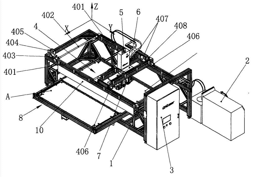
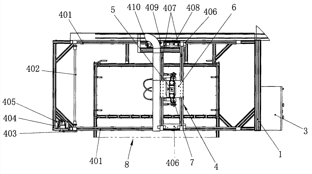
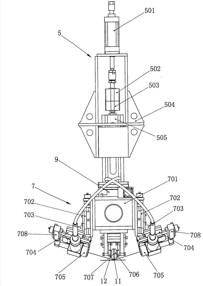
[0030] like figure 1 , 2 As shown, the present invention includes a frame 1, a solid-state pulse laser system 2 and a control system 3, the XY axis servo drive mechanism 4 is installed on the frame 1, and the main body of the frame 1 is made of standard aluminum alloy profiles, corner reinforcing members, etc. , High-strength bolts and washers are used to connect and fasten, and the plane on the upper part of the frame 1 is the reference plane for installing the XY-axis servo drive mechanism 4 . The Z-axis lifting mechanism 5 and the laser welding head 7 are mounted on the XY-axis servo drive mechanism 4 through the carriage 6 , a rotary table 8 is arranged under the laser welding head 7 , and a radiation isolation wall 10 is arranged on the frame 1 . The partition wall 10 is used to shield the laser radiation during welding and pr...


PUM

PropertyMeasurementUnit
poweraaaaaaaaaa

Abstract

The invention relates to a laser welding device of a solar flat plate collector. The laser welding device is characterized by comprising a frame, a solid pulse laser system and a control system. An XY-axis servo driving mechanism is arranged on the frame, a Z-axis lifting mechanism and a laser welding head are arranged on the XY-axis servo driving mechanism through a dragging plate, and a rotating table is arranged below the laser welding head. The laser welding device adopts a high-power solid pulse laser system, a high-speed precise linear module is used as an XY-axis transmission guiding component, the device operates stably, device welding speed is increased, welding point density is increased, welding quality is improved, and heat transmission effect of the solar flat plate collector is improved. The Z-axis lifting mechanism adopts a series connection structure of three cylinders, the laser welding head is lifted and lowered stably in subsection mode, damage such as copper pipe dent is reduced, product quality is improved, and production cost is reduced. A double-station rotating table structure is adopted, operators do not need to walk back and forth, labor intensity is lowered, and production efficiency is increased.

Description

technical field [0001] The invention relates to a laser welding device, in particular to a laser welding device for a solar flat plate heat collector. Background technique [0002] Solar flat plate collectors composed of copper tubes and aluminum plates welded are more and more widely used due to their advantages of high heat exchange efficiency, high mechanical strength and long service life. However, due to the difficulty of welding such solar flat panel collectors, laser welding equipment is usually used for welding. The welding speed, the size of the welding point and the density of the welding point are all restricted. At the same time, the XY axis linear motion pair adopts steel structural parts, the self-weight of the components is large, the inertia of the start and stop actions is large, the movement speed and movement accuracy It is greatly restricted and also affects the welding speed. The welding speed of the equipment is only 3m / min, the solder joints are small...

Claims


Application Information

Patent Timeline
Patent Type & Authority Applications(China)
IPC IPC(8): B23K26/20B23K26/08B23K26/42B23K26/21B23K26/70
Inventor 袁宝兴
Owner WUXI QINENG WELDING EQUIP
Learn More