Method for rescuing broken wire during silicon wafer linear cutting
A wire cutting and silicon wafer technology, which is applied to fine working devices, working accessories, stone processing equipment, etc., can solve the problems of poor rescue success rate, unsatisfactory rescue effect, and inability to accurately and smoothly set the knife.
- Summary
- Abstract
- Description
- Claims
- Application Information
AI Technical Summary
Problems solved by technology
Method used
Image
Examples
Embodiment 1
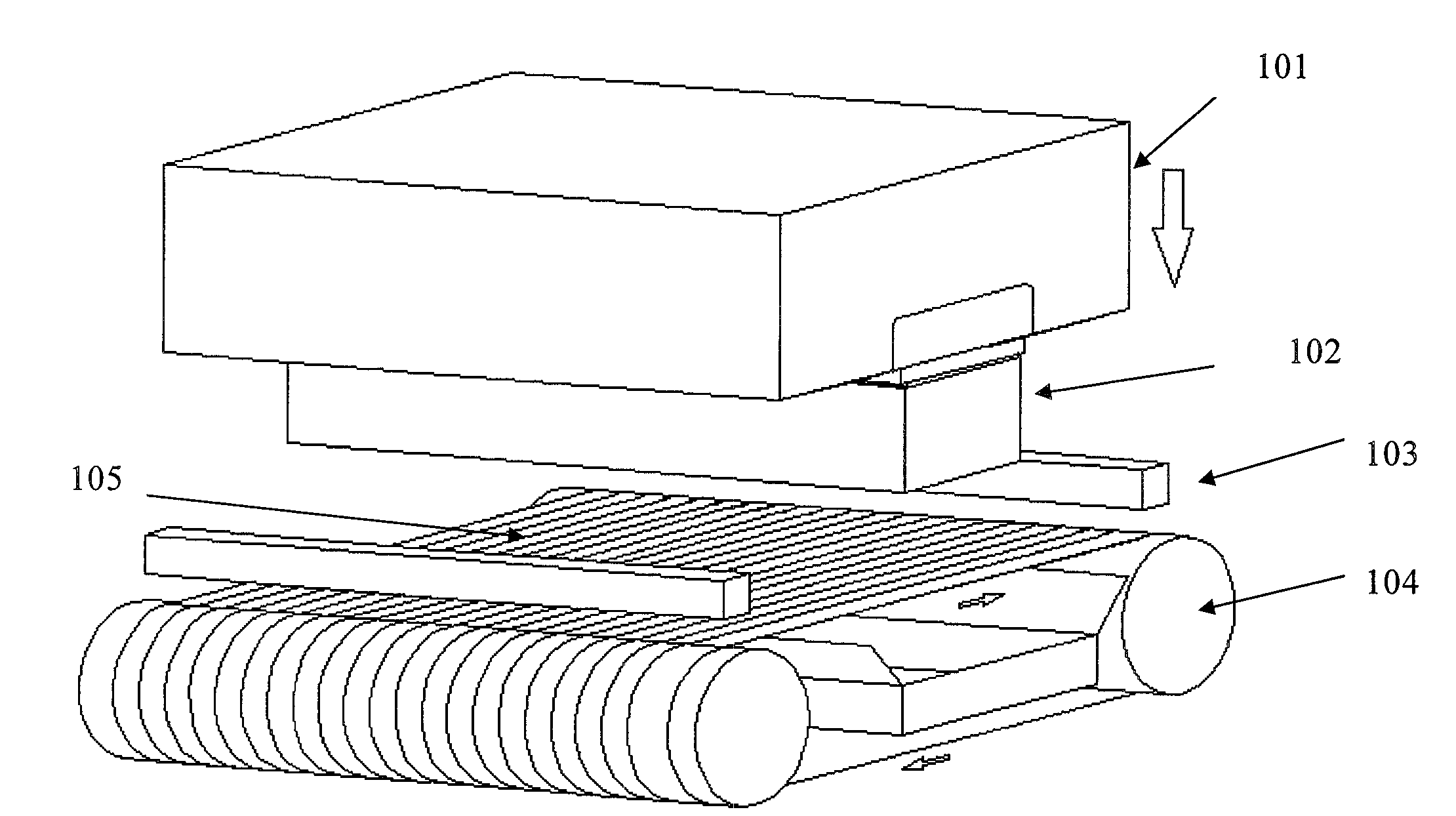
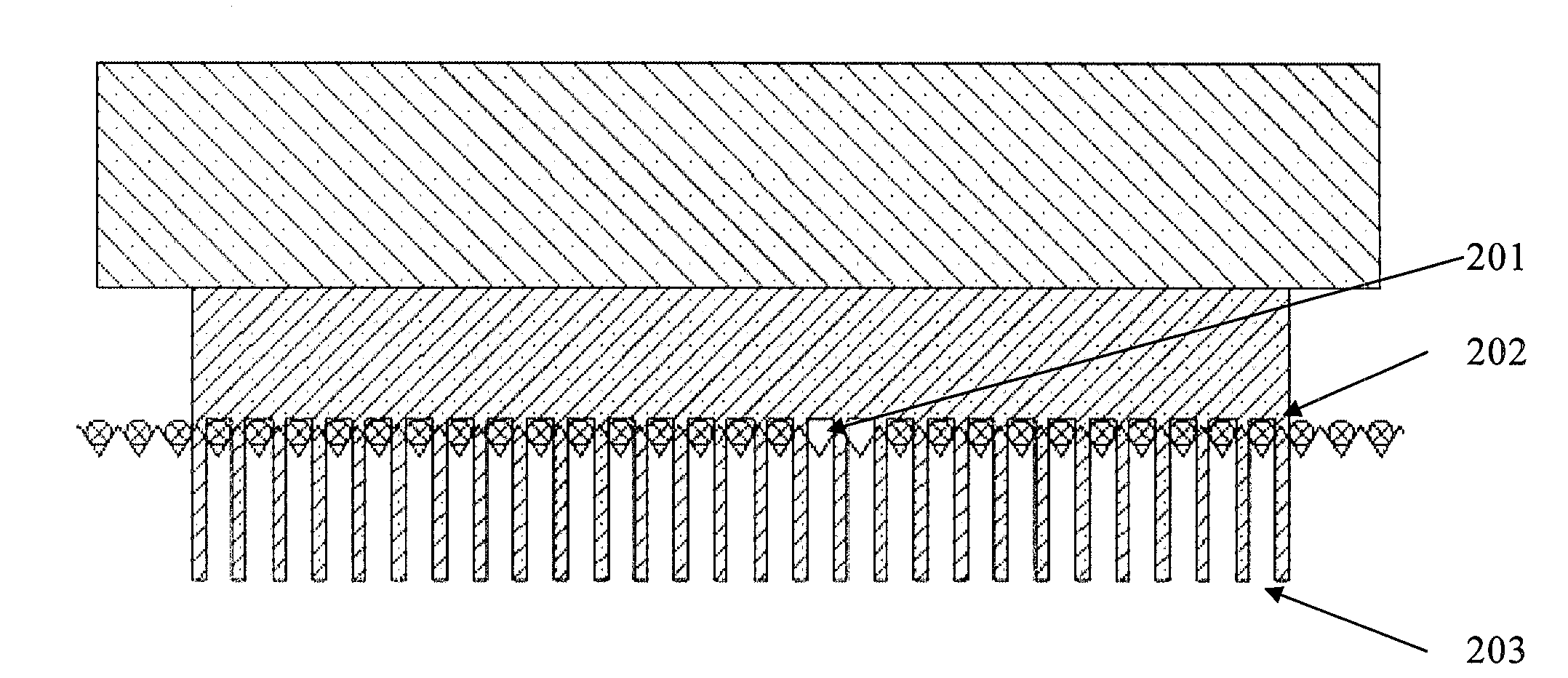
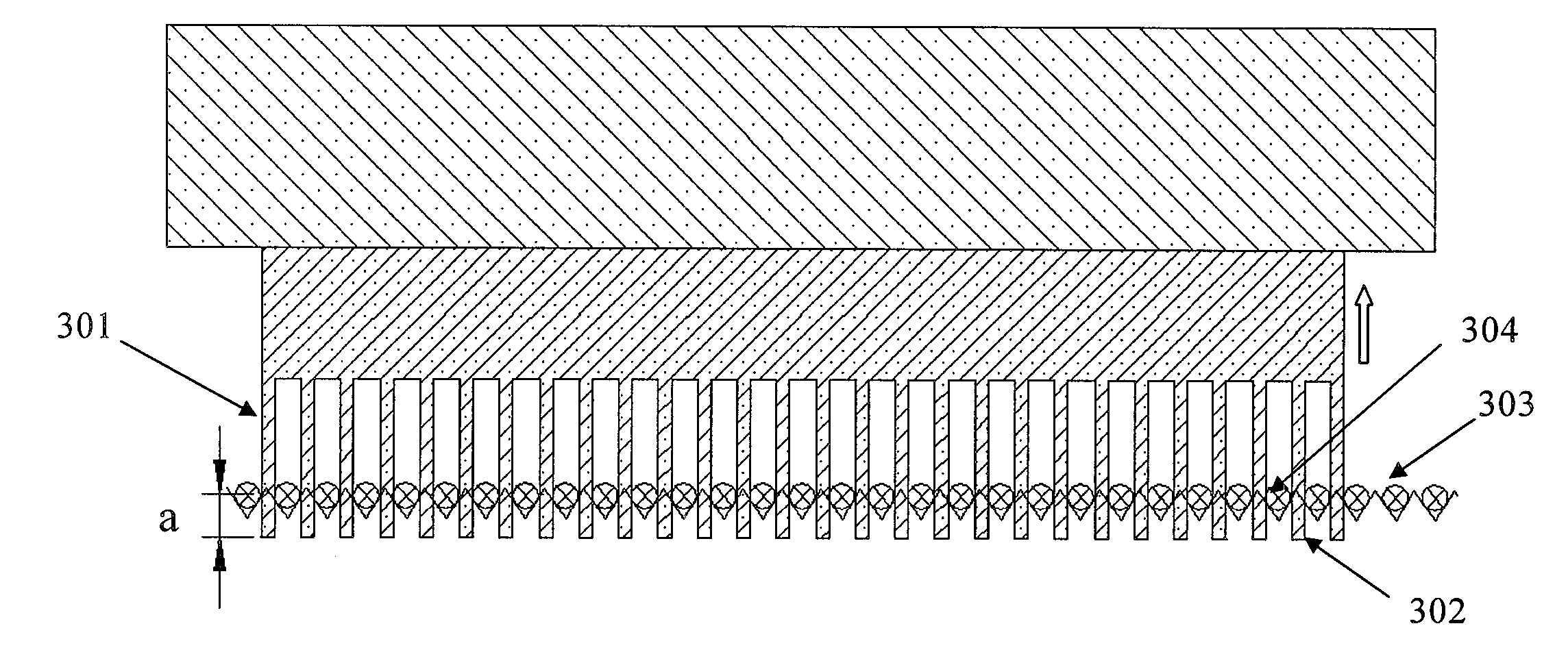
[0057] When the wire is broken at 50.588mm, the silicon ingot is raised at a speed of 10mm / min until the knife edge is located under the wire mesh and is about 20mm away from the wire mesh. Adjust the line speed to 0.5m / s and run 0.5m to level the line network. Open the mortar and rinse the silicon wafer evenly for 5 minutes, cut off the broken wire mesh, keep the steel wire in the gap of the silicon wafer, reserve 10-20mm wire mesh at the wire inlet end of the guide wheel head, rearrange the wire mesh and turn on the mortar back and forth to heat up, so that The new wiring network is fully covered with mortar, and then the silicon crystal rod is pressed down at a table speed of 5mm / min until the knife edge is located under the wire mesh and 6mm away from the wire mesh, and the steel wire segment left in the gap of the silicon wafer is removed. Then press down to the original cutting depth and then press down 0.5mm, level the wire mesh again at a line speed of 0.5m / s, let all ...
Embodiment 2
[0061] When a wire breakage occurs at a cut of 71.056mm, raise the silicon ingot at a speed of 10mm / min until the knife edge is located under the wire mesh and is about 16mm away from the wire mesh. Adjust the line speed to 0.5m / s and run 0.5m to level the line network. Open the mortar and rinse the silicon wafer evenly for 5 minutes, cut off the broken wire mesh, keep the steel wire in the gap of the silicon wafer, reserve 10-20mm wire mesh at the wire inlet end of the guide wheel head, rearrange the wire mesh and turn on the mortar back and forth to heat up, so that The new wiring network is fully covered with mortar, and then the silicon crystal rod is pressed down at a table speed of 5mm / min until the knife edge is located under the wire mesh and 6mm away from the wire mesh, and the steel wire segment left in the gap of the silicon wafer is removed. Then press down to the original cutting depth and then press down 0.5mm, level the wire mesh again at a line speed of 0.5m / s,...
Embodiment 3
[0065] When the wire is broken when the cutting is 106.103mm, the silicon ingot is lifted at a speed of 10mm / min until the knife edge is located under the wire mesh and is about 15mm away from the wire mesh. Adjust the line speed to 1m / s and run 0.5m to level the line network. Open the mortar and rinse the silicon wafer evenly for 5 minutes, cut off the broken wire mesh, keep the steel wire in the gap of the silicon wafer, reserve 10-20mm wire mesh at the wire inlet end of the guide wheel head, rearrange the wire mesh and turn on the mortar back and forth to heat up, so that The new wiring network is fully covered with mortar, and then the silicon crystal rod is pressed down at a table speed of 5mm / min until the knife edge is located under the wire mesh and 6mm away from the wire mesh, and the steel wire segment left in the gap of the silicon wafer is removed. Then press down to the original cutting depth and then press down 0.5mm, level the wire mesh again at a line speed of ...
PUM
 Abstract
Description
Claims
Application Information
 - R&D
- Intellectual Property
- Life Sciences
- Materials
- Tech Scout
- Unparalleled Data Quality
- Higher Quality Content
- 60% Fewer Hallucinations
Browse by: Latest US Patents, China's latest patents, Technical Efficacy Thesaurus, Application Domain, Technology Topic, Popular Technical Reports.
© 2025 PatSnap. All rights reserved.Legal|Privacy policy|Modern Slavery Act Transparency Statement|Sitemap|About US| Contact US: help@patsnap.com


