In-pipe concrete vacuum auxiliary filling method for large concrete-filled steel tubular structure and filling method

A technology of concrete-filled steel tubes and auxiliary systems, which is applied in the construction of buildings, construction, and the processing of building materials, etc., can solve the problems that affect the service performance of concrete-filled steel tube structures, cannot realize concrete pouring construction, and reduce the plasticity and fluidity of cement paste. Achieve the effect of improving mechanical properties and performance, reducing the number of defects, and reducing the number of bubbles

Active Publication Date: 2012-10-31
GUANGXI ROAD & BRIDGE ENG GRP CO LTD
View PDF4 Cites 14 Cited by
  • Summary
  • Abstract
  • Description
  • Claims
  • Application Information

AI Technical Summary

Problems solved by technology

However, this continuous pouring method cannot realize the concrete pouring construction of large-scale steel pipe concrete structures (long-span bridges, high-rise buildings, etc.), specifically, because the method is to continuously pour concrete in the pipe, due to the large-scale steel pipe concrete structure pipe span Large or super high, large concrete pouring volume and long pouring time. Before the concrete pouring in the structural pipe is completed, the concrete poured in the pipe has already set initially. After the initial setting of the concrete, the cement slurry in the concrete gradually loses Plasticity and fluidity start to coagulate into a gel until the cement slurry is completely gelled
During this process, if the formed gel breaks due to external force, the broken gel cannot close itself due to the decrease in the plasticity and fluidity of the cement slurry, which will eventually lead to defects such as cracks in the concrete in the obtained CFST structure. , and seriously affect the performance of all aspects of the steel pipe concrete structure, and even lead to the scrapping of the steel pipe concrete structure

Method used


Image

  • In-pipe concrete vacuum auxiliary filling method for large concrete-filled steel tubular structure and filling method
  • In-pipe concrete vacuum auxiliary filling method for large concrete-filled steel tubular structure and filling method
  • In-pipe concrete vacuum auxiliary filling method for large concrete-filled steel tubular structure and filling method

Examples


Embodiment Construction

[0058] The present invention will be described in further detail below in conjunction with the accompanying drawings, embodiments and test examples. However, it should not be understood that the scope of the above subject matter of the present invention is limited to the following embodiments, and all technologies realized based on the content of the present invention belong to the scope of the present invention.

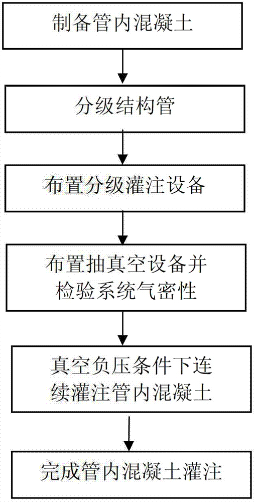
[0059] Such as figure 1 As shown, a vacuum-assisted pouring method for concrete in a large-scale concrete-filled steel tube structure (this embodiment is used for pouring the arch of a large-span concrete-filled steel tube arch bridge with a span of 500m), including the following steps:

[0060] (1) Preparation of high-performance concrete: use high-performance polycarboxylate water reducer, expansion agent and water reducer, adjust the mix ratio according to different concrete grades, so that the concrete slump reaches 180mm-240mm, the initial setting time 6 hours...


PUM

PropertyMeasurementUnit
slumpaaaaaaaaaa

Abstract

The invention discloses an in-pipe concrete vacuum auxiliary filling method for a large concrete-filled steel tubular structure and a filling method. The filling method comprises the following steps: preparing in-pipe concrete, grading structural pipes, placing graded filling devices, placing a vacuumizing device and checking gas tightness of the system, and grading and continuously filling in-pipe concrete under the vacuum negative pressure condition. The concrete is graded and filled, so that the influence of later filled concrete on coagulation of the filled concrete is avoided, and the mechanical property of the large concrete-filled steel tubular structure is improved, meanwhile, the requirement to the pumping capacity of the concrete pumping device is reduced; and the method and thesystem bring good economic effects. The concrete is filled continuously, so that the working period is shortened; under the negative pressure condition, the concrete is filled, thus the compactness of concrete and tightness of the concrete binding with the steel pipes are reinforced; and the quality of the steel pipe concrete structure is further improved.

Description

technical field [0001] The invention relates to a pouring method for a steel pipe concrete structure, in particular to a vacuum-assisted pouring method and a pouring system for concrete in a large steel pipe concrete structure. Background technique [0002] Steel tube concrete structure refers to the structural member formed by filling concrete in the steel tube, and the steel tube and its concrete can bear the external load together. According to the different cross-sectional shapes, it can be divided into circular steel tube concrete structure, square, rectangular steel tube concrete structure and polygonal Concrete Steel Tube Structures, etc. [0003] It is well known that concrete has excellent compressive strength, but its bending resistance is weak; steel, especially section steel, has good bending resistance and good elastic-plasticity, but it is easy to lose stability and lose axial compressive capacity when it is under compression . The concrete filled steel pipe ...

Claims


Application Information

Patent Timeline
Patent Type & Authority Applications(China)
IPC IPC(8): E04G21/02E04G21/06
Inventor 郑皆连韩玉秦大燕冯智罗业凤庞博新罗岩枫魏华赵吉卫王建军杨占峰陈光辉王劼耘牟廷敏朱云发张坤球林峰丁庆军龙跃
Owner GUANGXI ROAD & BRIDGE ENG GRP CO LTD
Why Eureka
Try Eureka