Kiln crown component of kiln

A kiln roof and component technology, applied in the direction of the furnace crown/roof, can solve the problems of no longer being used, affecting product quality, heavy quality, etc., and achieve the effects of reducing heat loss, significant energy saving effect, and improving service life

Inactive Publication Date: 2015-01-28
韩城腾龙陶瓷有限公司
View PDF7 Cites 0 Cited by
  • Summary
  • Abstract
  • Description
  • Claims
  • Application Information

AI Technical Summary

Problems solved by technology

The whole construction and installation is relatively complicated, and the quality requirements of construction personnel are high
[0005] 2. Because the traditional ceiling tiles are solid, they are not only heavy and easy to fall, but also the hooks and rings connecting the supports are made of stainless steel, which are prone to oxidation under long-term high temperature and cannot be used again. Generally, 1-2 year must be replaced
In addition, the high-performance adhesive used to bond ceiling tiles will fall off under long-term high temperature, causing dirt and affecting product quality. Therefore, traditional kiln roof materials generally have to be repaired and replaced once every 1-2 years
[0006] 3. Traditional ceiling tiles are generally full-body bricks, with a small number of holes in a few cases
The whole body brick mainly conducts heat through conduction, which has fast heat conduction and poor heat insulation effect. Therefore, the traditional suspended ceiling kiln roof structure heats up slowly, and the heat loss is also large during the heat preservation process, which wastes energy.

Method used


Image

  • Kiln crown component of kiln
  • Kiln crown component of kiln
  • Kiln crown component of kiln

Examples


Embodiment 1

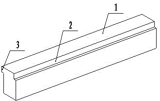
[0038] Such as figure 1 As shown, a kiln roof member, one side of the top of the main body beam 1 is provided with a groove 2, and the other side of the top of the main body beam 1 is provided with a bump 3 that is compatible with the size and shape of the groove 2;

[0039] The main body beam 1 is a square beam, and both the main body beam 1 and the bump 3 are solid.

Embodiment 2

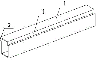
[0041] Such as figure 2 As shown, a kiln roof member, one side of the top of the main body beam 1 is provided with a groove 2, and the other side of the top of the main body beam 1 is provided with a bump 3 that is compatible with the size and shape of the groove 2;

[0042] The main body beam 1 is a square beam, and both the main body beam 1 and the bump 3 are hollow.

Embodiment 3

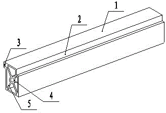
[0044] Such as image 3 As shown, a kiln roof member, one side of the top of the main body beam 1 is provided with a groove 2, and the other side of the top of the main body beam 1 is provided with a bump 3 that is compatible with the size and shape of the groove 2;

[0045] The main body beam 1 is a square beam, and both the main body beam 1 and the bump 3 are hollow;

[0046] A circular pipe 4 is arranged in the inner cavity of the hollow main body beam 1 , and at least one reinforcing rib 5 is used to connect the round pipe 4 with the inner wall of the hollow main body beam 1 .

[0047] This kind of structure is stable and reliable. After the kiln roof is built according to the following method of use according to the present invention, multiple present inventions are self-contained and are not easy to break, and even if there is an accidental breakage, the curved sealing part overlapping with the adjacent present invention It can bear a part of the self-weight of the brok...


PUM


Abstract

The invention provides a kiln crown component of a kiln, and belongs to the technical field of kiln crown bricks of kilns. The kiln crown component of the kiln is light in weight, convenient to install, and has long service life. The technical scheme is that a groove is arranged at one side of the top of a main body beam, and a bump in match with the groove in size and shape is arranged at the other side of the top of the main body beam; the main body beam is hollow, or solid; the bump is hollow, or solid; the main body beam is a quadrate beam; a circular tube is arranged in an internal cavity of the hollow main body beam; the circular tube is connected with the internal wall of the hollow main body beam through at least one reinforcing rib plate; the main body beam is a plate-shaped beam; at least one upright separating plate is distributed in the internal cavity of the hollow main body beam; a reinforcing rib is arranged in a cavity which is formed between the internal wall of the hollow main body beam and the upright separating plate; and the top or the bottom of the main body beam is flat or arched. The kiln crown component is especially suitable for building the kiln crowns of industrial kilns.

Description

technical field [0001] The invention relates to a kiln roof component, which belongs to the technical field of kiln roofs. Background technique [0002] The kiln roof of the existing industrial kiln is usually a ceiling type, and the structure is divided into five layers: the top layer is a steel frame, and the hook connected to the steel frame is the second layer, and the hook hooks the fifth layer of ceiling tiles (for example: the thickness is 230mm, 230mm long, 65mm wide mullite ceiling tiles (ρ=1.0) to reduce the weight of the ceiling tiles, the third and fourth layers are perlite (about 200mm thick) and fire-resistant blanket (for example: 100mm thick The left and right aluminum silicate standard blankets) are spread evenly on the ceiling tiles of the fifth floor. The third, fourth, and fifth floors are the main refractory insulation layers on the top of the kiln. The first layer of steel frames and the second layer of hooks It mainly plays the role of support and red...

Claims


Application Information

Patent Timeline
Patent Type & Authority Patents(China)
IPC IPC(8): F27D1/02
Inventor 万锦标
Owner 韩城腾龙陶瓷有限公司
Why Eureka
Try Eureka