Laser beam shaping method and device
A laser beam and spot technology, applied in laser welding equipment, optics, optical components, etc., can solve the problems of changing the shape of the spot and the size and distribution of power density, and achieve the effects of low production cost, easy manufacture, and simple structure
- Summary
- Abstract
- Description
- Claims
- Application Information
AI Technical Summary
Problems solved by technology
Method used
Image

Examples
Embodiment 1
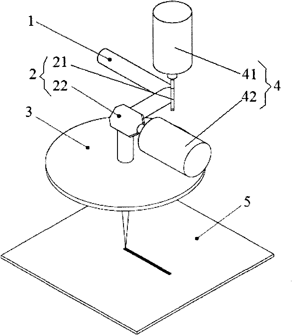
[0042] like figure 1As shown, the laser beam shaping device according to an embodiment of the present invention includes a reflective optical device 2 , a focusing optical device 3 and a driving mechanism 4 . More specifically, the reflective optical device 2 includes a first reflector 21 and a second reflector 22, and the drive mechanism 4 includes a first drive mechanism 41 and a second drive mechanism 42, and the first drive mechanism 41 is used to drive the first reflector 21 , for example to drive the first reflector 21 to rotate, and the second drive mechanism 42 is used to drive the second reflector 22 , for example to drive the second reflector 22 to rotate.
[0043] In an example of the present invention, the first driving mechanism 41 and the second driving mechanism 42 may be motors, and the focusing optical device 3 may be a focusing lens, preferably, the focusing lens is an f-theta lens.
[0044] The incident laser beam 1 is reflected by the first reflector 21 to...
Embodiment 2
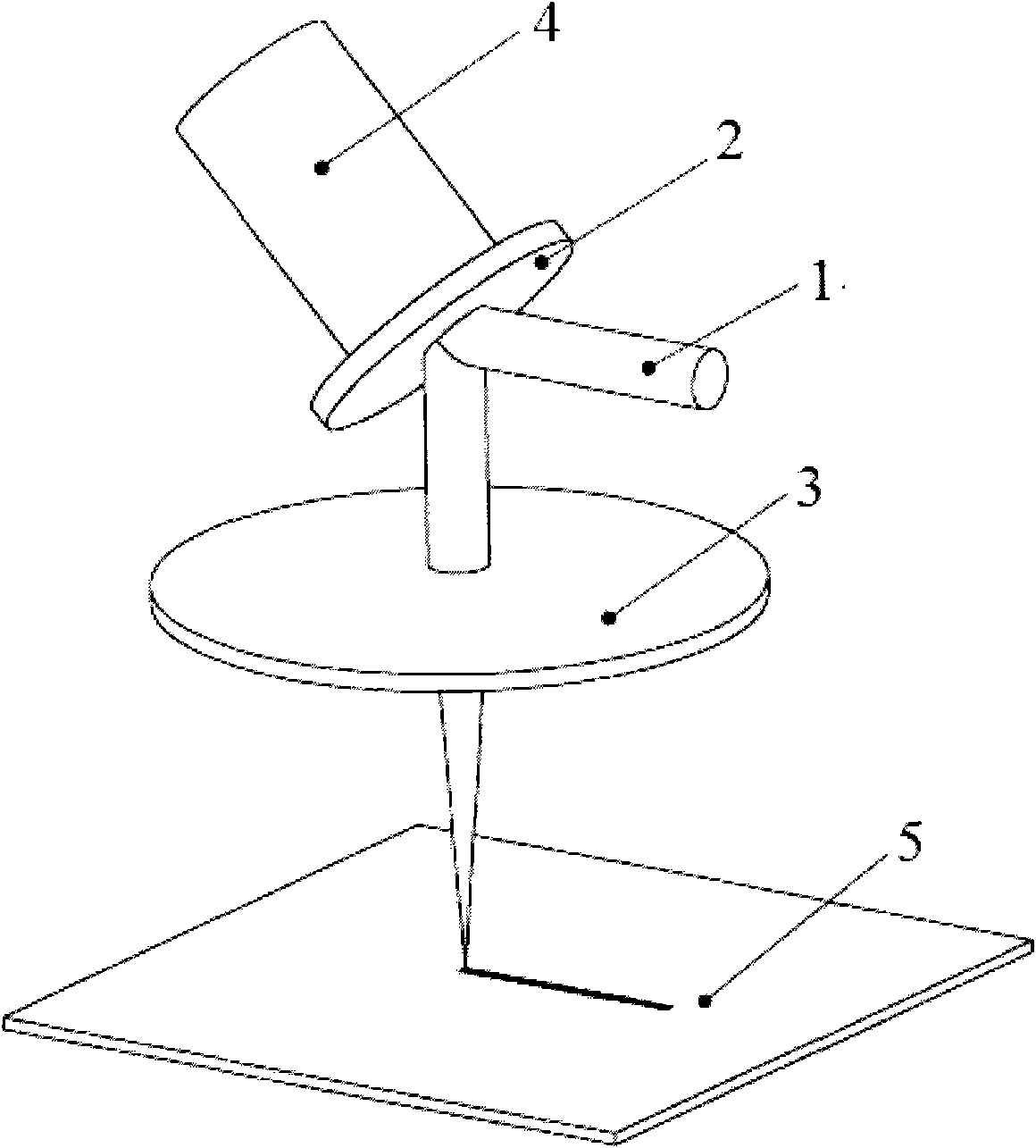
[0048] Such as figure 2 As shown, the laser beam shaping device according to another embodiment of the present invention includes a reflective optical device 2 , a focusing optical device 3 and a driving mechanism 4 . Specifically, the reflecting optical device 2 is a mirror, the driving structure 4 is a moving platform, the focusing optical device 3 is a focusing mirror, and the reflecting mirror 2 is installed on the moving platform 4 . Preferably, the motion platform 4 may be a piezoelectric ceramic motion platform, and the focusing mirror 3 may be an f-theta mirror.
[0049] The laser beam 1 reaches the focusing mirror 3 after being reflected by the reflector 2, and the focusing mirror 3 focuses the laser beam 1 onto the processing material 5 to form a spot. Through the method of programming, the motion platform 4 can be controlled to move with a predetermined two-dimensional or three-dimensional trajectory, for example, leaning forward, backward or swinging left and rig...
Embodiment 3
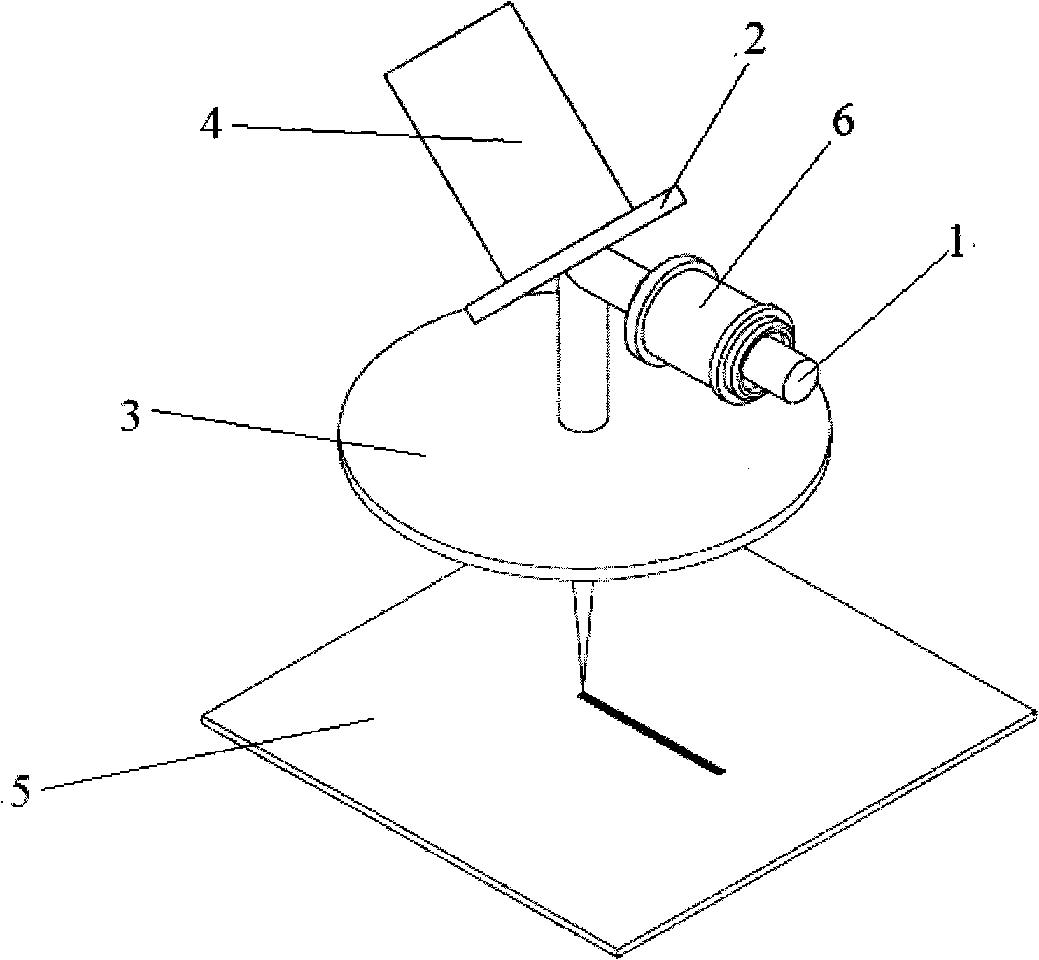
[0053] Such as image 3 As shown, the laser beam shaping device according to yet another embodiment of the present invention includes: a reflective optical device 2 , a focusing optical device 3 , a driving mechanism 4 and a diffractive optical device 6 . Specifically, the reflecting optical device 2 may be a mirror, the driving structure 4 may be a moving platform, the focusing optical device 3 may be a focusing mirror, and the reflecting mirror 2 is installed on the moving platform. Preferably, the motion platform is a piezoelectric ceramic motion platform, and the focusing mirror is an f-theta mirror.
[0054] The laser beam 1 forms a beam with a predetermined shape after being diffracted by the diffractive optical device 6, such as a rectangle, an ellipse, etc., and then the beam with a predetermined shape reaches the focusing mirror 3 after being reflected by the reflecting mirror 2, and passes through the focusing mirror 3. After focusing, a light spot of a predetermine...
PUM
 Abstract
Description
Claims
Application Information
 - Generate Ideas
- Intellectual Property
- Life Sciences
- Materials
- Tech Scout
- Unparalleled Data Quality
- Higher Quality Content
- 60% Fewer Hallucinations
Browse by: Latest US Patents, China's latest patents, Technical Efficacy Thesaurus, Application Domain, Technology Topic, Popular Technical Reports.
© 2025 PatSnap. All rights reserved.Legal|Privacy policy|Modern Slavery Act Transparency Statement|Sitemap|About US| Contact US: help@patsnap.com