Direct feed omnidirectional printed antenna with radiation load

A printed antenna and radiating technology, which is applied in antennas, antenna arrays, radiating element structures, etc., can solve the problems that omnidirectional antennas cannot meet the requirements of good omnidirectionality, high gain, and wide bandwidth at the same time, and achieve simple structure and low power feeding The form is compact and the effect of reducing the out-of-roundness of the pattern

Active Publication Date: 2012-10-31
HARBIN INST OF TECH
View PDF0 Cites 2 Cited by
  • Summary
  • Abstract
  • Description
  • Claims
  • Application Information

AI Technical Summary

Problems solved by technology

[0004] The purpose of the present invention is to provide a direct-fed omnidirectional printed antenna with a radiating load, so as to solve the problem that the current omnidirectional antenna cannot satisfy the requirements of good omnidirectionality, wide bandwidth and high gain at the same time.

Method used


Image

  • Direct feed omnidirectional printed antenna with radiation load
  • Direct feed omnidirectional printed antenna with radiation load
  • Direct feed omnidirectional printed antenna with radiation load

Examples


specific Embodiment approach 1

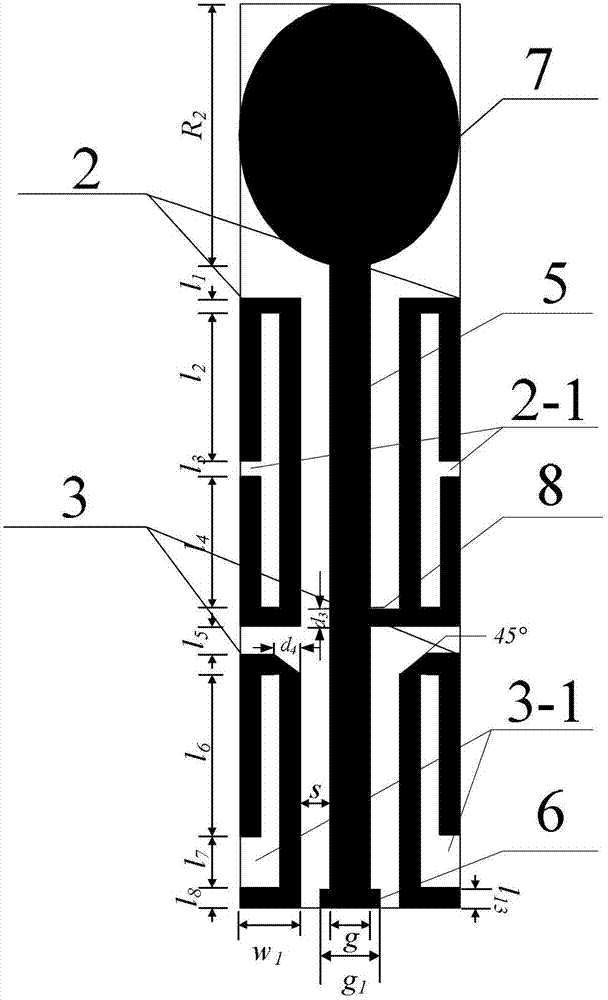
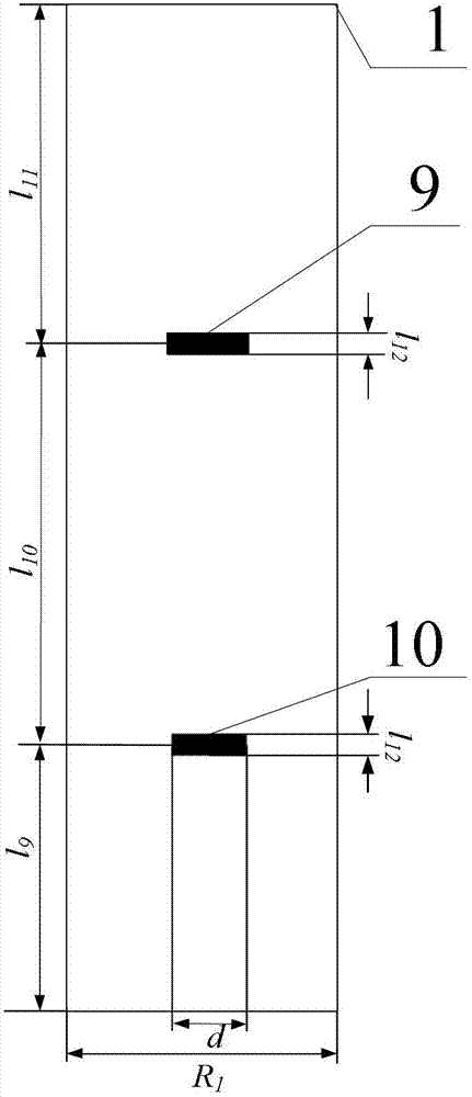
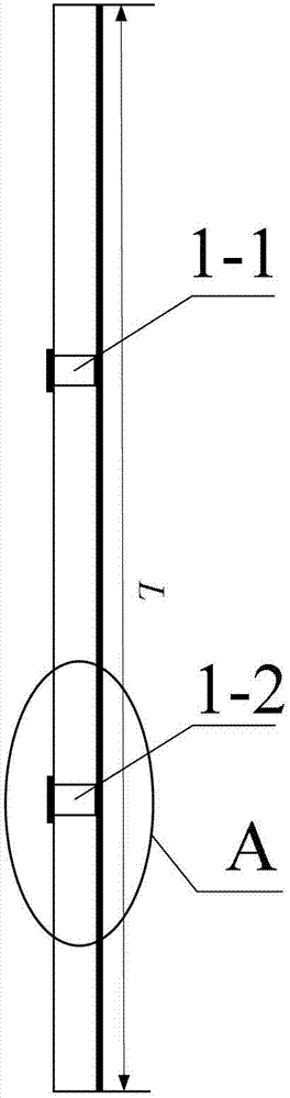
[0008] Specific implementation mode one: combine Figure 1-Figure 10 Describe this embodiment, the antenna of this embodiment includes a dielectric plate 1 and a coplanar waveguide central feeder 5, and the antenna also includes two groups of vibrators, a feeding port matching branch 6, a radial terminal load 7, a first horizontal feeder 8, The second horizontal feeder 9 and the third horizontal feeder 10, two groups of oscillators, the coplanar waveguide central feeder 5, the feeding port matching branch 6, the radial terminal load 7 and the first horizontal feeder 8 are printed on the front side wall of the dielectric board 1 , the second horizontal feeder 9 and the third horizontal feeder 10 on the rear side wall of the dielectric board 1, the lower end of the coplanar waveguide central feeder 5 is connected to the feeding port matching stub 6, the upper end of the coplanar waveguide central feeder 5 is connected to the radial terminal The load 7 is connected, and each grou...

specific Embodiment approach 2

[0013] Specific implementation mode two: in conjunction with figure description 1- Figure 10 To illustrate this embodiment, the radial terminal load 7 of this embodiment is elliptical, isosceles trapezoidal or combined, wherein the combined shape is composed of a rectangle and a semicircle, and the short side of the rectangle coincides with the diameter of the semicircle. The terminal radiation load is an elliptical load, which plays a role that ordinary loads do not have, that is, radiates electromagnetic waves, so that the gain of the antenna is further improved. The semicircular and coplanar waveguide center feeders in the combined load realize gradual transition; the load of the trapezoidal load antenna adopts an isosceles trapezoid to ensure symmetry. Other implementation manners are the same as the specific implementation manner 1.

specific Embodiment approach 3

[0014] Specific implementation mode three: in conjunction with figure description 1 and Figure 7 To illustrate this embodiment, a 45° isosceles right triangle is cut off at the apex position of each second vibrator 3 close to the coplanar waveguide center feeder 5 in this embodiment, and cutting the isosceles right triangle can reduce the antenna feeder. reflection to achieve better matching, other implementations are the same as the first implementation.


PUM


Abstract

The invention discloses a direct feed omnidirectional printed antenna with a radiation load, which relates to a printed antenna, in particular to an omnidirectional radiation printed antenna, and is used for solving the problem of incapability of simultaneously meeting the requirements of high omnidirectional radiation, large bandwidth and high gain existing in the conventional omnidirectional antenna. The lower end of a coplanar waveguide central feeder line is connected with a feeding port matching branch knot; the upper end of the coplanar waveguide central feeder line is connected with a radiation terminal load; a first vibrator and a second vibrator are mouth-shaped; one side of the first vibrator which is far away from the coplanar waveguide central feeder line is provided with a first square through hole; one side of the second vibrator which is far away from the coplanar waveguide central feed line is provided with a second square through hole; a second horizontal feeder line is connected with the first vibrator through two first metal through holes; and a third horizontal feeder line is connected with the second vibrator through two second metal through holes. The direct feed omnidirectional printed antenna is applied to the field of point-to-multipoint communication of a C waveband.

Description

technical field [0001] The invention relates to a printed antenna, in particular to an omnidirectional radiation printed antenna. Background technique [0002] The printed antenna is an antenna made with modern printed circuit board technology. The omnidirectional antenna is an antenna that has basically no difference in radiation characteristics in the horizontal plane, but has directional radiation in the vertical plane, that is, on the horizontal pattern. It is manifested as 360° uniform radiation, which is commonly referred to as non-directional. Since the development of omnidirectional antennas, there have been various changes in structural forms, from the initial monopole and dipole to biconical and helical antennas, etc., and there are mainly two feeding methods: parallel feed and series feed. Way. It is widely used in some special communication systems such as point-to-multipoint base station-to-terminal communication and satellite communication system. [0003] O...

Claims


Application Information

Patent Timeline
Patent Type & Authority Applications(China)
IPC IPC(8): H01Q1/38H01Q13/00H01Q21/00
Inventor 林澍林怡琛刘曦刘梦芊马欣茹陆加田雨荆丽雯
Owner HARBIN INST OF TECH
Why Eureka
Try Eureka