Three-level three-phase power source transformation device capable of initiatively balancing clamp voltage of neutral points
A technology of neutral point clamping and neutral point voltage, applied in the direction of output power conversion device, AC power input conversion to DC power output, electrical components, etc., can solve strong electromagnetic interference, control complexity, multi-harmonic And other issues
- Summary
- Abstract
- Description
- Claims
- Application Information
AI Technical Summary
Problems solved by technology
Method used
Image
Examples
Embodiment 1
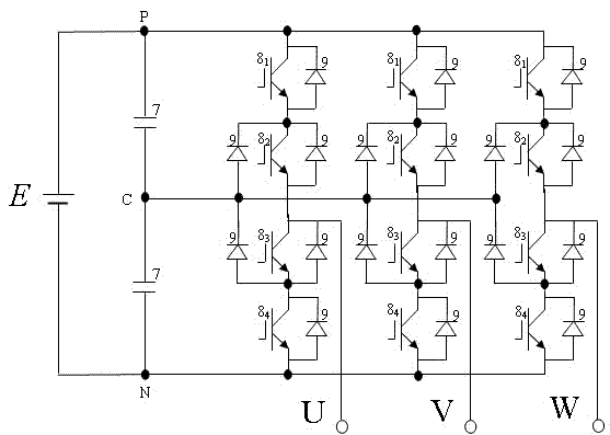
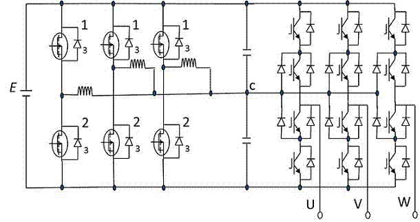
[0020] Example 1, such as figure 2 It is a circuit diagram showing the main circuit configuration of the three-level inverter device with the device for suppressing the neutral point current shift of the present embodiment. Such as figure 2 As shown, this example is composed of two parts, the first part is a three-phase neutral point clamped three-level PWM inverter device, the second part is a device that actively balances the neutral point clamping voltage, and the active balance The neutral point clamp voltage device connects the high-frequency switching element 1 in series between the positive bus and the neutral line, connects the high-frequency switching element 2 in series between the neutral line and the negative bus, and connects the two high-frequency switching elements in parallel for freewheeling The diode 3 is connected in series with the inductor 4 between the two high-frequency switching elements and the neutral point c of the three-phase neutral-point clampe...
Embodiment 2
[0026] Embodiment 2, secondly, with reference to Figure 6 A three-level three-phase power conversion device capable of actively balancing neutral point clamp voltages according to Embodiment 2 of the present invention will be described. Figure 6 It is a circuit diagram showing a main circuit configuration of a three-level three-phase power conversion device capable of actively balancing neutral point clamp voltages according to Embodiment 2 of the present invention. The difference between the three-level three-phase power conversion device that can actively balance the neutral point clamp voltage in this embodiment and the three-level three-phase power conversion device that can actively balance the neutral point clamp voltage in the above embodiment is that: Between the busbar and the negative busbar are connected 3 devices for actively balancing the neutral point clamping voltage described in the above example, and each device for actively balancing the neutral point clamp...
Embodiment 3
[0027] Embodiment 3 illustrates another three-level three-phase power conversion device of the present invention that can actively balance the neutral point clamp voltage. Figure 7 It is a circuit diagram showing the main circuit structure of the three-level three-phase power conversion device capable of actively balancing the neutral point clamp voltage of this embodiment. The difference between the three-level three-phase power conversion device that can actively balance the neutral point clamp voltage in this embodiment and the three-level three-phase power conversion device that can actively balance the neutral point clamp voltage in the above embodiment is that: When the power supply of the phase-neutral point clamped three-level PWM inverter device is rectified input, the positive bus of the device that actively balances the neutral point clamped voltage and the three-phase neutral point clamped three-level PWM inverter A diode is connected in series between the positiv...
PUM
 Abstract
Description
Claims
Application Information
 - R&D
- Intellectual Property
- Life Sciences
- Materials
- Tech Scout
- Unparalleled Data Quality
- Higher Quality Content
- 60% Fewer Hallucinations
Browse by: Latest US Patents, China's latest patents, Technical Efficacy Thesaurus, Application Domain, Technology Topic, Popular Technical Reports.
© 2025 PatSnap. All rights reserved.Legal|Privacy policy|Modern Slavery Act Transparency Statement|Sitemap|About US| Contact US: help@patsnap.com


