Power conversion device

A technology of power conversion device and power converter, which is applied in the direction of controlling electromechanical transmission device, output power conversion device, electronic commutation motor control, etc., can solve the problems of smoothing capacitor damage, motor current ripple, pulsation, etc., and achieve improved stability sex, reduce the effect of pulsation

Active Publication Date: 2012-10-31
HITACHI IND PROD LTD
View PDF7 Cites 6 Cited by
  • Summary
  • Abstract
  • Description
  • Claims
  • Application Information

AI Technical Summary

Problems solved by technology

Therefore, in the synchronous PWM control in which the frequency ft of the triangular wave carrier is switched depending on the change of the fundamental frequency ft of the phase voltage command value, there is a problem that pulsation (switching shock) occurs when the number of pulses is switched.
In particular, when the number of pulses is small (for example, 9 pulses to 3 pulses), in addition to the problem of the switching shock, there is also a problem that due to the control cycle accompanying the sharp change of the triangular wave carrier frequency fc after switching The drastic change of the control system becomes unstable
As a result, problems such as damage to the smoothing capacitor and ripples in the motor current occur.

Method used


Image

  • Power conversion device
  • Power conversion device
  • Power conversion device

Examples


Embodiment approach 1

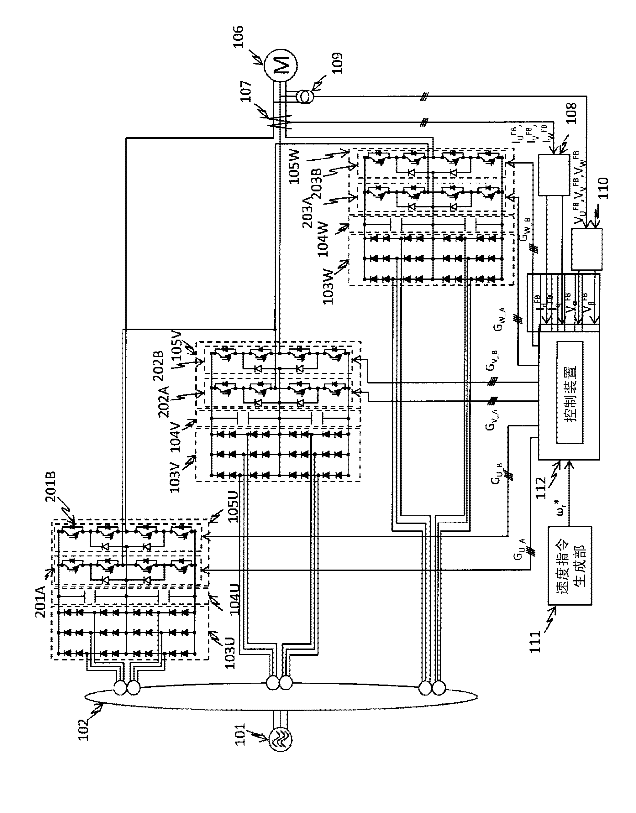
[0057] figure 1 The first embodiment of the present invention is shown. in figure 1 Here, the AC voltage supplied by the three-phase AC power supply 101 is transformed by the transformer 102, rectified by the diode parts 103U, 103V, and 103W, and smoothed by the smoothing capacitors 104U, 104V, and 104W to obtain the DC voltage.

[0058] The 5-stage power converter 105U obtained by connecting single-phase 3-stage power converters 201A and 201B in series, the 5-stage power converter 105V obtained by connecting single-phase 3-stage power converters 202A and 202B in series, and the single-phase 3-stage power converter 105V The five-stage power converter 105W obtained by connecting the power converters 203A and 203B in series converts the DC voltage into AC of arbitrary frequency and phase, and supplies it to the AC motor 106 to perform variable speed control of the AC motor.

[0059] The output current detector 107 detects the U-phase, V-phase, and W-phase output currents in the AC ...

Embodiment approach 2

[0086] Next, regarding the second embodiment of the present invention, the differences from the first embodiment will be described. In Embodiment 1, the number of pulses is set to a multiple of 3, but as Figure 14 As shown, all integer pulses added with integers other than multiples of 3 can be used.

[0087] When the number of pulses is set as in the present embodiment, when the number of pulses is not a multiple of 3, the phase voltage command value V of the V phase and W phase V * , V W * With the positive side triangular wave carrier C u , The negative side triangle wave carrier C d The comparison of carrier waveform is as Figure 15 Shown, T VI Period and t VII Output voltage during the period V V , And, T WI Period and t WII Output voltage during the period V W It is asymmetrical with respect to the axis 401. So like Figure 16 As shown, by making the positive side triangular wave carrier C u , The negative side triangle wave carrier C d The phase shift of +120°, or -12...

Embodiment approach 3

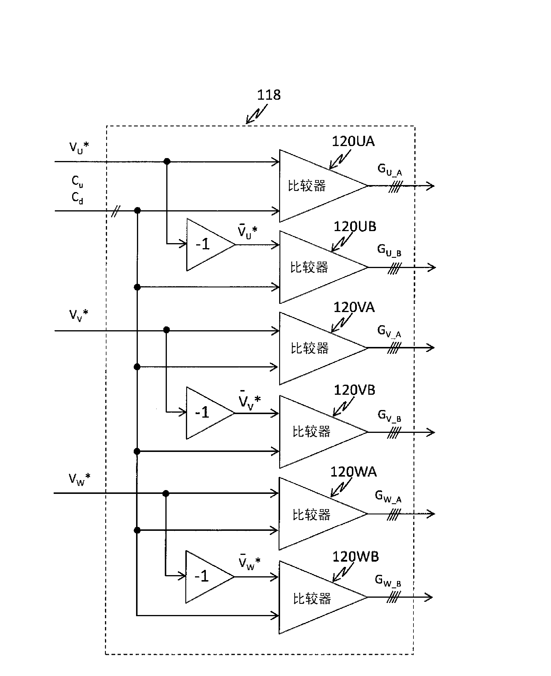
[0092] Next, regarding the third embodiment of the present invention, the differences from the first and second embodiments will be described. In the first embodiment, for the strobe signal G U_A , G U_B , Set two positive-side triangular wave carriers C of the same waveform with different offset values u , The negative side triangle wave carrier C d , Through the phase voltage command value V U * , -V U * Compare to output, but it can also be as Figure 17 As shown, a triangular wave carrier is set, the phase voltage command values ​​with different offset values ​​are made, compared with the carrier waveform, and the strobe signal G is output U_A , G U_B . At this time, the offset value is the distance between the peak and the trough of the triangular wave carrier. Figure 17 Set to 1. By changing the phase voltage command value V U * , -V U * Such as Figure 17 As shown moves upward, the distance between the peak and the trough of the triangular wave carrier is 1, so that the ...


PUM


Abstract

The invention provides a power conversion device which comprises a plurality of power converters capable of converting alternating current power supply voltage to direct current voltage and converting the converted direct current voltage to alternating current voltage and can output a plurality of stages of alternating voltage through combination of alternating current outputs of the plurality of power converters, The power conversion device comprises a PWM modulator. The PWM modulator compares a carrier signal of triangular wave and a phase voltage instruction of sine wave and thus performs PWM control of the power converters which converting the direct current voltage to the alternating current voltage. The ratio between the frequency of the carrier signal of the triangular wave input in the PWM modulator and the frequency of the phase voltage instruction may be odd multiples of 3, even multiples of 3, and integral multiples of 3 except for the odd multiples and the even multiples. In the plurality of stages of the power conversion devices or tandem multiple power conversion devices characterized by synchronous PWM control, the stability of a system can be improved through increase of degree of freedom of setting of the frequency (fc) of the carrier wave of the triangular wave.

Description

Technical field [0001] The present invention relates to a power conversion device, and more particularly to a power conversion device that performs pulse width modulation control on a DC voltage based on a phase voltage command value to convert it into an AC voltage of an arbitrary frequency. Background technique [0002] In an AC motor drive using a power conversion device, the AC power supplied from the commercial power source is rectified by a diode inside the power conversion device, and smoothed by a smoothing capacitor to convert it into a DC voltage. After that, it is converted into an arbitrary AC voltage by the inverter and output to the motor for variable speed control. [0003] Specifically, the inverter is switched in accordance with PWM control based on the comparison of the phase voltage command value and the magnitude of the triangular wave carrier to convert the magnitude of the sinusoidal phase voltage command value into an output pulse, and a voltage is applied to...

Claims


Application Information

Patent Timeline
Patent Type & Authority Applications(China)
IPC IPC(8): H02M7/5395H02P27/06H02M7/48H02M7/483H02P21/00H02P21/18H02P21/22H02P21/24H02P23/16H02P25/22H02P27/04H02P27/08H02P27/14
Inventor 伊藤雄太名仓宽和永田浩一郎秋田佳稔阿部重幸
Owner HITACHI IND PROD LTD
Why Eureka
Try Eureka