Gas-liquid separator combining centrifugal separation, baffle flow direction change and porous medium filtration

A gas-liquid separator and porous media technology, applied in separation methods, dispersed particle separation, combined devices, etc., can solve the problems of high pressure drop, difficult to effectively improve the separation degree, and no efficient combination of gas-liquid separators, etc. The effect of meeting the separation requirements and having a simple and compact structure

Active Publication Date: 2012-11-07
TECHNICAL INST OF PHYSICS & CHEMISTRY - CHINESE ACAD OF SCI
View PDF5 Cites 10 Cited by
  • Summary
  • Abstract
  • Description
  • Claims
  • Application Information

AI Technical Summary

Problems solved by technology

A common structural form is that the direction of the baffle is changed multiple times, which uses the blocking effect of the multi-channel baffles arranged in the flow direction on the gas-liquid mixture to force the liquid to suddenly change direction, so that the tiny droplets in the airflow are condensed and separated. The horizontal oil separator is usually used in screw compressor units for refrigeration with more oil content. The disadvantage is that the size of the gas-liquid separator is large, and the separation degree is difficult to effectively improve; another common structural form is centrifugal , which utilizes the density difference between gas and liquid, and through the high-speed swirl of the gas-oil mixture, the liquid droplets accumulate on the wall of the separator. It is usually used in vertical oil separation equipment such as compressed air, and its disadvantage is that the pressure drop is high , and the variable flow characteristics are poor; another common structural form is porous media filtration, which utilizes the principle that the porous media has different gas-liquid flow characteristics to make the liquid phase condense inside it, and is usually used, for example, in the post-stage precision of compressed air The disadvantage is that the pressure drop is high, and it is not suitable for occasions with high liquid content
Usually according to actual needs, there are also cases where the above methods are used in combination, such as connecting a horizontal baffle or a vertical centrifugal gas-liquid separator in series with a porous media filter to achieve better separation of gas and liquid, but it has not been possible to combine the above methods Structural form of gas-liquid separator with efficient combination of three methods

Method used


Image

  • Gas-liquid separator combining centrifugal separation, baffle flow direction change and porous medium filtration

Examples


Embodiment 1

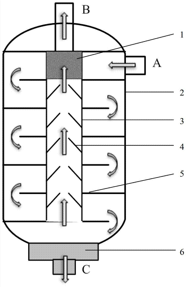
[0023] The upper and lower ends of the cylindrical separator housing 2 (diameter of 40 centimeters and height of 1 meter) placed vertically in the axial direction of this embodiment are respectively equipped with a top cover and a bottom oil collection chamber 6; 4 horizontal baffles 5 on the inner wall of the body 2 are staggered; To the center; a hollow cylindrical cavity 3 is installed in the axial center of the cylindrical separator housing 2, and the hollow cylindrical cavity 3 passes through each horizontal baffle plate 5 in turn, and the vertical inner wall of the hollow cylindrical cavity 3 5 conical baffle plates 4 with upper openings distributed up and down are installed on the top; a cylindrical adsorption filter 1 is installed on the upper end of the hollow cylindrical cavity 3; one side of the upper part of the cylindrical separator housing 2 is provided with The mixed gas inlet A connected to it; the top of the cylindrical separator housing 2 is provided with the...

Embodiment 2

[0026] The upper end and the lower end of the cylindrical separator housing 2 (60 cm in diameter and 1.5 m in height) placed vertically in the axial direction of this embodiment are equipped with a top cover and a bottom oil collection chamber 6 respectively; 20 horizontal baffles 5 on the inner wall of the cylindrical separator housing 2 are placed in a staggered manner; the horizontal baffles 5 are located below the top cover of the cylindrical separator housing, and the outer edges of the horizontal baffles 5 exceed the cylinder The radial center of the separator housing 2; a hollow cylindrical cavity 3 is installed in the center of the cylindrical separator housing 2; the hollow cylindrical cavity 3 passes through each baffle in turn, and the hollow cylindrical cavity 3 25 conical baffles 4 with upper openings distributed up and down are installed on the inner wall; a cylindrical adsorption filter 1 is installed on the upper end of the hollow cylindrical cavity 3; Mixed ga...

Embodiment 3

[0028] This embodiment is basically the same as Embodiment 1, except that there is one horizontal baffle and three conical baffles.


PUM


Abstract

The invention discloses a gas-liquid separator combining centrifugal separation, baffle flow direction change and porous medium filtration, which comprises an axially vertically arranged cylindrical separator housing, a top cover, a bottom oil collecting cavity, at least one horizontal baffle distributed up and down, a cylindrical absorption filter and a hollow cylindrical cavity body, wherein the top cover and the bottom oil collecting cavity are respectively arranged at the upper end and lower end of the housing; the horizontal baffle is arranged on the inner wall of the housing; the outer edge of the horizontal baffle exceeds the radial center of the housing; the cylindrical absorption filter is arranged on the lower end face of the top cover; the hollow cylindrical cavity body is arranged on the axial center of the housing; the hollow cylindrical cavity body sequentially penetrates through the horizontal baffle from bottom to top, and the upper end of the hollow cylindrical cavity body is connected with the cylindrical absorption filter; at least one cone-shaped baffle distributed up and down is arranged on the inner wall of the hollow cylindrical cavity body, and the upper end of the cone-shaped baffle is provided with an opening; one side of the upper part of the housing is provided with a mixed gas inlet; the top end of the housing is provided with a refrigerant outlet; and the lower end of the bottom oil collecting cavity is provided with a lubricating oil outlet. The gas-liquid separator has a simple and compact structure, can integrate multiple separation effects of impaction, condensation capturing, gravity settling and absorption filtration, and meets the high-efficiency separation requirement of the lubricating oil and a refrigerant.

Description

technical field [0001] The invention relates to a gas-liquid separator, in particular to a gas-liquid separator combined with centrifugal separation, baffle plate variable flow direction and porous medium filtration. Background technique [0002] Gas-liquid separation is widely used in many fields, such as oil-water separation of compressed air, oil-gas separation in refrigeration field, high-efficiency separation of components with large boiling point differences in many chemical processes, etc., all require the use of various types of gas liquid separator. Especially in the new multi-component mixed working medium precooling system driven by oil-lubricated compressors that has been developed rapidly in recent years, the oil-gas separation of the pre-stage oil directly affects the process structure and long-term operation stability of the system. [0003] There are many commonly used gas-liquid separator structures. A common structural form is that the direction of the ba...

Claims


Application Information

Patent Timeline
IPC IPC(8): B01D50/00B01D19/00
Inventor 吴剑峰公茂琼董学强沈俊
Owner TECHNICAL INST OF PHYSICS & CHEMISTRY - CHINESE ACAD OF SCI
Why Eureka
Try Eureka