Vacuum box for applying load in vacuum to manufacture vacuum thermal insulation plate

A technology of vacuum insulation panels and loading, which is applied to flat products, household appliances, other household appliances, etc., can solve problems such as increased operating costs, collapse of vacuum insulation panels, increase in thermal conductivity, etc., to shorten the vacuuming time, the overall The effect of good flatness and reduced thermal conductivity

Inactive Publication Date: 2014-07-02
寇博伦
View PDF4 Cites 0 Cited by
  • Summary
  • Abstract
  • Description
  • Claims
  • Application Information

AI Technical Summary

Problems solved by technology

[0004] Limited by technical conditions, the current vacuum insulation panel manufacturing equipment uses molds to press and shape insulation material particles, put them into vacuum bags, and then enter the box for vacuum treatment. However, since the insulation material particles have been pressed and formed, This virtually increases the time of vacuuming and increases the operating cost. At the same time, because the insulation forming board is placed horizontally in the box, the insulation material particles at the opening of the vacuum bag are easily sucked out by the vacuum system during vacuuming. In this way, the sucked out Insulation material particles will not only pollute the vacuum pumping system, but also a large number of insulation material particles will be bonded to the heat-sealing joint of the vacuum bag, resulting in poor heat-sealing effect of the insulation bag, and the unevenness of the insulation material after molding increases the thermal conductivity , wasting energy
[0005] The vacuum insulation panels made by the existing manufacturing equipment, in the process of use, once the vacuum bag is damaged and broken, the vacuum insulation panels in the vacuum bag are very easy to be damp, the vacuum insulation panels will leak, the thermal conductivity will increase greatly, and even the vacuum insulation will appear. Panel collapse accident, shortening the practical life of vacuum insulation panels

Method used


Image

  • Vacuum box for applying load in vacuum to manufacture vacuum thermal insulation plate
  • Vacuum box for applying load in vacuum to manufacture vacuum thermal insulation plate
  • Vacuum box for applying load in vacuum to manufacture vacuum thermal insulation plate

Examples


Embodiment Construction

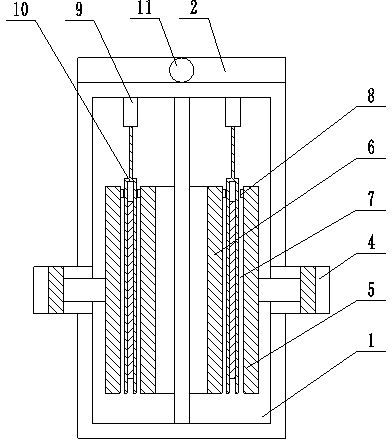
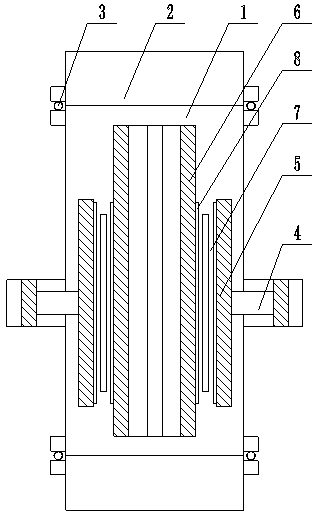
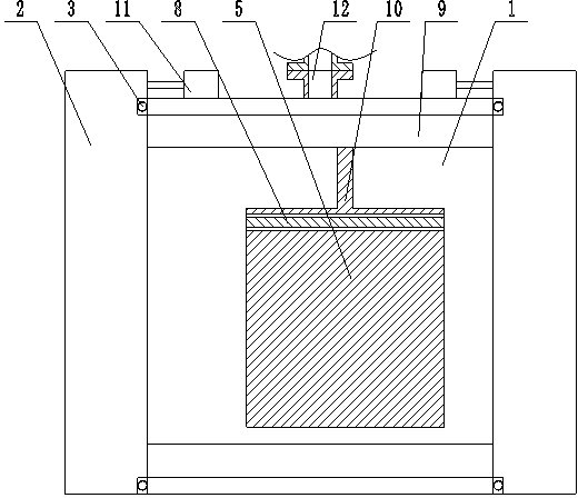
[0023] Such as figure 1 , figure 2 , image 3 As shown, the present invention applies load in vacuum to manufacture the vacuum box of the vacuum insulation panel. Both ends of the box body 1 are provided with airtight doors 2, and the upper part of the airtight door 2 is hinged on the top of the box body 1 through door shafts. The two hydraulic cylinders 11 are all symmetrically arranged at both ends of the top of the box body 1, and the piston rods of each second hydraulic cylinder 11 are hinged on the corresponding sealing door 2, and the mating surfaces of each sealing door 2 and the box body 1 are uniform. A seal 3 is provided;

[0024] Both sides of the box body 1 are provided with a plurality of first hydraulic cylinders 4, and the plurality of first hydraulic cylinders 4 correspond to each other and their piston rods are arranged oppositely. On the piston rod of each of the first hydraulic cylinders 4 Both are fixedly provided with a pressure plate 5, a support plat...


PUM


Abstract

The invention relates to a vacuum box for applying load in vacuum to manufacture a vacuum thermal insulation plate, belongs to the technical field of manufacture of vacuum thermal insulation plates, and overcomes the shortcomings in the prior art. The vacuum box for applying the load in vacuum to manufacture the vacuum thermal insulation plate cannot leak air or fall easily and is good in flatness, low in coefficient of heat conductivity, short in vacuum-pumping time and low in manufacturing cost. To solve the technical problems, the technical scheme is that air-tight doors are arranged at two ends of a box body, a plurality of second hydraulic oil cylinders are symmetrically arranged at two ends of the top of the box body, a plurality of first hydraulic oil cylinders are arranged on two sides of the box body, pressure plates are fixedly arranged on piston rods of the first hydraulic oil cylinders, and electric heating sealing strips are arranged at corresponding positions of the pressure plates and support plates. A guide rail is arranged on a top wall of the box body, a clamp is movably arranged on the guide rail, and a vacuum-pumping system is further arranged on the top wall of the box body. The vacuum box is mainly used for processing the vacuum thermal insulation plate.

Description

technical field [0001] The invention discloses a vacuum box for manufacturing a vacuum heat insulation panel by adding a load in vacuum, and belongs to the technical field of vacuum heat insulation panel manufacture. Background technique [0002] At present, most of the thermal insulation materials used in the market are organic materials with poor fireproof performance, while the materials used in vacuum insulation panels have good fireproof performance, are Class A non-combustible, and have low thermal conductivity, so vacuum insulation panels are ideal thermal insulation materials. Has a broad market prospect. [0003] Vacuum insulation panel is a thermal insulation material with a thermal conductivity of 0.004W / (m k), and its thickness is thin, generally around 17mm. Under the same thermal conductivity conditions, it is thicker than conventional thermal insulation materials. It is smaller and has a wider range of applications, such as refrigerators, refrigerated contain...

Claims


Application Information

Patent Timeline
Patent Type & Authority Patents(China)
IPC IPC(8): B29C51/10B29L7/00
Inventor 寇亚明寇博伦陈秀凯李晓森
Owner 寇博伦
Why Eureka
Try Eureka