
New-energy cold and heat air exchange system of air conditioner for automobile

A new energy vehicle and air exchange technology, applied in air handling equipment, vehicle parts, heating/cooling equipment, etc., can solve the problems of energy efficiency ratio of only 1.3-1.6, insufficient processing accuracy, battery consumption, etc.

Inactive Publication Date: 2012-11-07
江苏晨宇车业有限公司
View PDF5 Cites 6 Cited by
  • Summary
  • Abstract
  • Description
  • Claims
  • Application Information

AI Technical Summary

Problems solved by technology

[0002] The core component of the known domestic new energy vehicle air-conditioning cooling and heating air exchange system: the technical route of the electric compressor is a direct current inverter alternating current—AC inverter drives a permanent magnet brushless motor, and is directly connected to the integrated compressor of the scroll compressor machine, there are generally problems of unstable drive circuit, backward machining equipment, insufficient processing accuracy, low output power, and the energy efficiency ratio of electric compressors is only about 1.3-1.6, so it is difficult to enter the market in batches
The electric air-conditioning system with low energy efficiency will consume a lot of battery energy, which may reduce the continuous capacity of new energy vehicles by 50%! Therefore, it is imminent to develop a high-efficiency heating and cooling air exchange system for new energy vehicles!

Method used


Image

  • New-energy cold and heat air exchange system of air conditioner for automobile
  • New-energy cold and heat air exchange system of air conditioner for automobile
  • New-energy cold and heat air exchange system of air conditioner for automobile

Examples


Embodiment 1

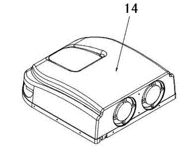
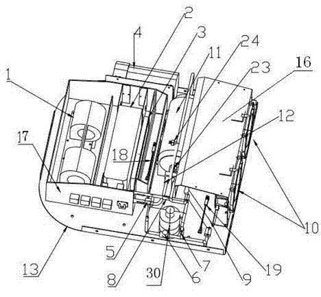
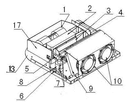
[0033] Taking the overhead electric air conditioning system as an example, the system is designed in a streamlined shape based on the principles of aerodynamics and aesthetics. The front end is an evaporator box, and the air inlet and outlet are connected to the top of the car at the bottom. The evaporator adopts a high heat transfer effect stacked structure (parallel flow structure can also be used), and the heat transfer power reaches 6kw. The evaporator fan adopts DC brushless centrifugal Fan, stepless speed regulation, power 120w, maximum air volume 500 cubic meters per hour. The rear end is a condenser, which adopts a double-layer parallel flow structure, and the heat exchange power reaches 8kw; the condensing fan is two 8-inch axial flow brushless fans that draw air backwards, each fan has a power of 100w, and the total air volume reaches 1800 cubic meters per hour. There are enough large and beautiful air inlets on the left and right front and middle parts of the casing...


PUM


Abstract

The invention discloses a new-energy cold and heat air exchange system of an air conditioner for an automobile, which comprises an evaporator (2), a condenser (9), an electric compressor (11) and a dry liquid storage tank (30) connected through a pipeline 1 (5) to form a closed system, arranged in a box body and controlled by an electronic control system, wherein the front part of the box body is provided with an evaporation case (17); the rear part of the box body is provided with a condensing case (16); and the middle part of the box body is provided with the electronic control system. The new-energy cold and heat air exchange system is characterized in that the refrigeration process is that a refrigerant is gasified by the evaporator (2), then enters the electric compressor (11), the condenser (9), and the dry liquid storage tank (30) and enter the evaporator (2) again to disperse the cold air into inside of a compartment, so that the refrigeration is finished. In the whole circulating process, the electric compressor plays a role of compressing and delivering steam of the refrigerant; the electronic digital control panel computes according to parameters of each sensor through a mathematical model and experiential data, accurately controls the rotation speed of the electric compressor, the opening degree of an electronic expansion valve and reasonable air quantity of a fan, so that the system is kept at the best working state.

Description

technical field [0001] The invention relates to a new energy vehicle used for power electronics, high-energy motors, cooling and heating energy exchange, and a mechanical and electrical integrated air conditioning cooling and heating air exchange system. Background technique [0002] The core component of the known domestic new energy vehicle air-conditioning cooling and heating air exchange system: the technical route of the electric compressor is a direct current inverter alternating current—AC inverter drives a permanent magnet brushless motor, an integrated compressor directly connected to the scroll compressor Machines, there are generally problems such as unstable driving circuit, backward machining equipment, insufficient processing accuracy, low output power, and the energy efficiency ratio of electric compressors is only about 1.3-1.6, so it is difficult to enter the market in batches. The electric air-conditioning system with low energy efficiency will consume a lo...

Claims


Application Information

Patent Timeline
Patent Type & Authority Applications(China)
IPC IPC(8): B60H1/00
Inventor 张亚军官永雄
Owner 江苏晨宇车业有限公司
Learn More