Vortex generating device

A eddy current generation and eddy current technology, which is used in the separation of dispersed particles, chemical instruments and methods, separation methods, etc., can solve the problems of easy fouling, blockage and poisoning of catalysts, and large investment costs of catalysts, so as to reduce construction investment and operating costs. , the effect of reducing the dosage

Active Publication Date: 2012-11-14
南通常安能源有限公司
View PDF4 Cites 1 Cited by
  • Summary
  • Abstract
  • Description
  • Claims
  • Application Information

AI Technical Summary

Problems solved by technology

The disadvantages are: the investment cost of the catalyst during the construction period is relatively large, accounting for about 60% of the construction investment; the catalyst is easy to accumulate dust during production, causing blockage and poisoning
It is bound to cost a certain cost to reach a certain height

Method used


Image

  • Vortex generating device
  • Vortex generating device
  • Vortex generating device

Examples


Embodiment Construction

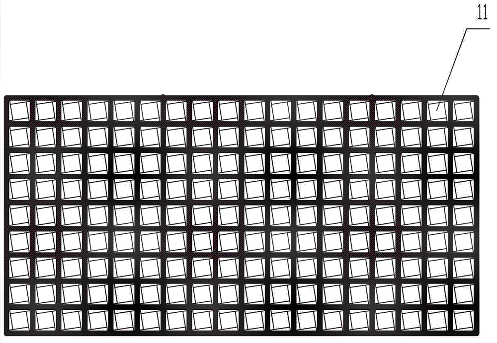
[0030] Figure 1~6 Provide a kind of vortex generator, it is characterized in that: comprise n (such as figure 1 Shown as 9×15) the vortex generating units 11 are arranged in a rectangular shape.

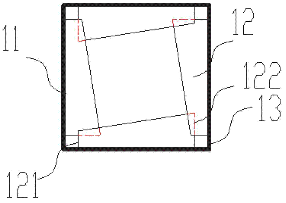
[0031] Each vortex generating unit 11 includes a square channel formed by four partitions 13 of the same size, that is, the cross section of the square channel is a square. The height (ie, depth) of the square channel is 200-500 mm, and the side length of the cross section of the square channel is 80-200 mm.

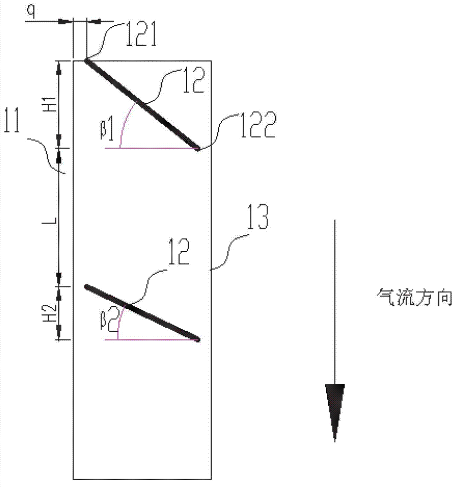
[0032] Two vortex guide vane assemblies are arranged along the airflow direction in the square channel, that is, the first vortex guide vane assembly (that is, close to the air inlet) and the second vortex guide vane assembly (that is, away from the air inlet, near the air outlet), The 2-stage vortex guide vane assemblies are spaced from each other.

[0033] The structure of each vortex guide vane assembly is as follows:

[0034] Each stage of the vortex guide vane assemb...


PUM


Abstract

The invention discloses a vortex generating device comprising at least one vortex generating unit (11). Each vortex generating unit (11) comprises a square channel set up by four clapboards (13) with the same size, and at least one level of vortex guide vane component is arranged in the square channel along the airflow direction. Each level of vortex guide vane component is composed of four flat-plate-type vortex generating vanes (12), and each flat-plate-type vortex generating vane (12) is fixed on the inner surface of each clapboard (13) and is vertical to the clapboard (13) connected with the vane (12). The vortex generating device is additionally arranged on a body of a denitration device, thus flue gas can penetrate through a catalyst layer in a vortex state so as to prolong the contact time of the flue gas with a catalyst and further realize the purposes of reducing the height of the catalyst and reducing the cost.

Description

technical field [0001] The invention relates to a flue gas denitrification treatment project, and in particular provides a rectifying device used in the flue gas SCR denitrification process. Background technique [0002] SCR is currently the most mature flue gas denitrification technology. It is a post-furnace denitrification method. It was first commercially operated in Japan in the late 1960s and 1970s. It uses a reducing agent (NH 3 , urea) under the action of metal catalysts, selectively react with NOx to generate N 2 and H 2 O, instead of being O 2 Oxidation, so it is called "selectivity". At present, the world's popular SCR technology is mainly divided into two types: ammonia method SCR and urea method SCR. These two methods use the reduction function of ammonia to NOx, and under the action of catalyst, NOx (mainly NO) is reduced to N which has no pollution effect on the atmosphere. 2 and water. [0003] There are three types of catalysts used for SCR denitrifi...

Claims


Application Information

Patent Timeline
Patent Type & Authority Applications(China)
IPC IPC(8): B01D53/90B01D53/56
Inventor 吴祖良楼军孙培德俞鑫飞楼琦
Owner 南通常安能源有限公司
Why Eureka
Try Eureka