Engine starting cam shaft assembly

A technology of engine starting and camshaft, which is applied in the direction of engine components, machines/engines, mechanical equipment, etc., can solve the problem of poor finish of aluminum pins or soft iron pins, affecting the flexibility of centrifugal flying weights, and the reliability of centrifugal flying weights Poor quality and other problems, to achieve the effect of saving space and materials, conducive to controllability, and conducive to mass production

Active Publication Date: 2012-11-14
重庆澳强工贸股份有限公司
View PDF4 Cites 0 Cited by
  • Summary
  • Abstract
  • Description
  • Claims
  • Application Information

AI Technical Summary

Problems solved by technology

[0004] 1) The cost of the torsion spring is high, the assembly is difficult, the assembly operation is difficult, the labor intensity of the workers is high, and the assembly efficiency is not high
[0005] 2) The controllability of mass production is poor, the torsion spring is easily damaged during the assembly process, and the torsion stability of the torsion spring in actual use is poor, so the reliability of driving the centrifugal flying weight is also not good
Aluminum pins or soft iron pins have low hardness, are prone to deformation or damage, and have a short service life; and the finish of aluminum pins or soft iron pins is not good, and the frictional resistance between them and the centrifugal flying weight is large, which will affect the centrifugal flying weight. Flexibility of block movement

Method used


Image

  • Engine starting cam shaft assembly
  • Engine starting cam shaft assembly
  • Engine starting cam shaft assembly

Examples


Embodiment Construction

[0023] Below in conjunction with accompanying drawing and embodiment the present invention will be further described:

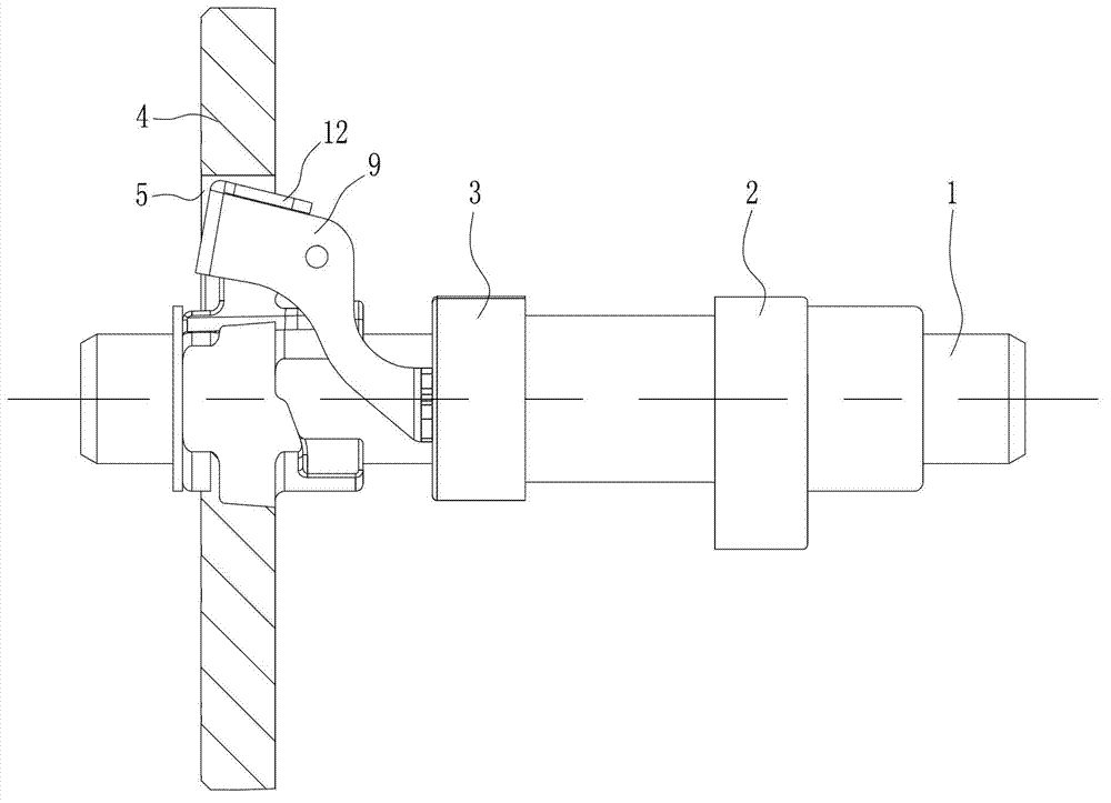
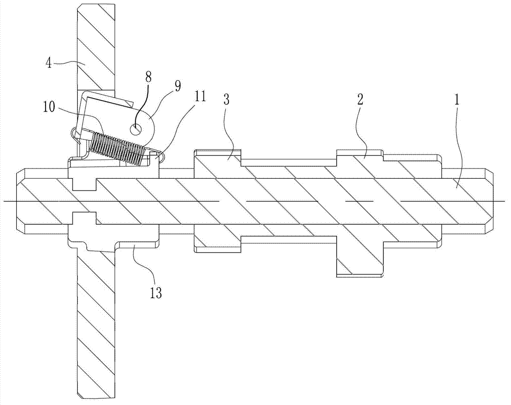
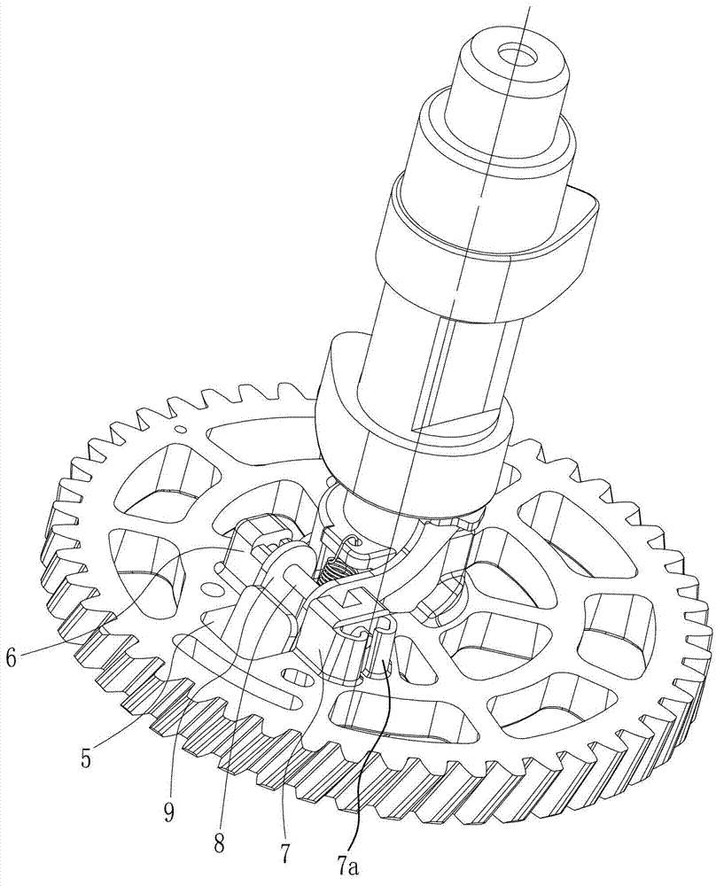
[0024] Such as figure 1 , figure 2 , image 3 , Figure 4 Shown, the present invention consists of camshaft 1, intake cam 2, exhaust cam 3, drive gear 4, first pin seat 6, second pin seat 7, pin shaft 8, centrifugal flying block 9, reset extension spring 10, Hole seat 11, counterweight 12 and annular boss 13 etc. constitute. Wherein, the intake cam 2, the exhaust cam 3 and the drive gear 4 are all sleeved on the camshaft 1, and the installation method of each wheel is the same as that of the prior art, and will not be repeated here. The driving gear 4 is also called the timing gear, and the driving gear 4 is close to the shaft end of the camshaft 1, and the driving gear 4 and the intake cam 2 are separated on both sides of the exhaust cam 3. An annular boss 13 is arranged on the end face of the driving gear 4 facing the exhaust cam 3 , the annular boss ...


PUM


Abstract

The invention discloses an engine starting cam shaft assembly. A first pin base (6) and a second pin shaft (7) are arranged on the end face of a driving gear (4); a centrifugal flyweight (9) is hinged between the first pin base (6) and the second pin base (7) through a pin shaft (8); the pin shaft (8) is a steel straight round pin; a resetting tension spring (10) is arranged between the pin shaft (8) and a cam shaft (1); and one end of the resetting tension spring (10) is connected with the centrifugal end of the centrifugal flyweight (9), and the other end of the resetting tension spring (10) is connected with a hole base (11) arranged on the driving gear (4). The engine starting cam shaft assembly provided by the invention has the advantages of simple and compact structure, less parts, and convenience and rapidness of assembly. Not only can space and materials be saved, but also the controllability in batch production is good; and the operation reliability can be effectively improved. According to the engine starting cam shaft assembly provided by the invention, the centrifugal flyweight is mounted by using the steel straight round pin, so that not only can the pin shaft be prevented from deformation or damage, but also the friction resistance between the pin shaft and the centrifugal flyweight can be reduced.

Description

technical field [0001] The invention belongs to the technical field of engines, and in particular relates to a starting camshaft assembly on an engine. Background technique [0002] General-purpose small gasoline engines require simple structure and low cost, and are often manually started. When starting, if the cylinder pressure at the timing point is too high, the working load of the engine will be large when the engine starts running, which will cause severe rebound and may cause injury to the operator. Therefore, it is necessary to set a decompression device to properly reduce the pressure in the cylinder to facilitate the normal starting operation of the engine. [0003] Chinese patent ZL 201020579696.5 disclosed an engine start decompression device on May 18, 2011. The start decompression device includes a camshaft on which an intake cam, an exhaust cam and a driving gear are arranged. There is a through hole, and pin seats are set on both sides of the through hole. ...

Claims


Application Information

Patent Timeline
IPC IPC(8): F01L13/08
Inventor 唐德胜陈跃华谭图廖新生
Owner 重庆澳强工贸股份有限公司
Why Eureka
Try Eureka