Kinematic transformation based grinding machining method for numerically controlled grinding wheel

A processing method and a technology of grinding wheel grinding, which are applied to metal processing equipment, grinding/polishing equipment, and parts of grinding machine tools, can solve deviations, reduce the geometric accuracy and dimensional accuracy of processed workpieces, and do not consider the geometric accuracy and dimensional accuracy of CNC grinding machines. Problems such as the influence of dimensional accuracy

Active Publication Date: 2012-11-21
HUAZHONG UNIV OF SCI & TECH
View PDF7 Cites 20 Cited by
  • Summary
  • Abstract
  • Description
  • Claims
  • Application Information

AI Technical Summary

Problems solved by technology

However, for the CNC grinding method of the prior art, there are still the following defects: due to the kinematic characteristics and geometric errors of the CNC grinding machine itself, it is easy to cause a discrepancy between the actual trajectory of the grinding point and the ideal trajectory of the grinding wheel during the grinding process. Large deviation, and directly lead to the problem of the reduction of the geometric accuracy and dimensional accuracy of the processed workpiece
[0004] However, the above methods do not consider the influence of the CNC grinding machine based on its own kinematic characteristics and geometric error deviation on the geometric accuracy and dimensional accuracy of the workpiece.
Therefore, the problem of motion deviation of the grinding point cannot be effectively solved, and there is a need for further improvement in order to improve the quality of the grinding process

Method used


Image

  • Kinematic transformation based grinding machining method for numerically controlled grinding wheel
  • Kinematic transformation based grinding machining method for numerically controlled grinding wheel
  • Kinematic transformation based grinding machining method for numerically controlled grinding wheel

Examples


Embodiment Construction

[0049] In order to make the object, technical solution and advantages of the present invention clearer, the present invention will be further described in detail below in conjunction with the accompanying drawings and embodiments. It should be understood that the specific embodiments described here are only used to explain the present invention, not to limit the present invention.

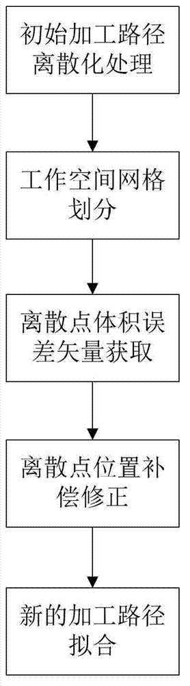
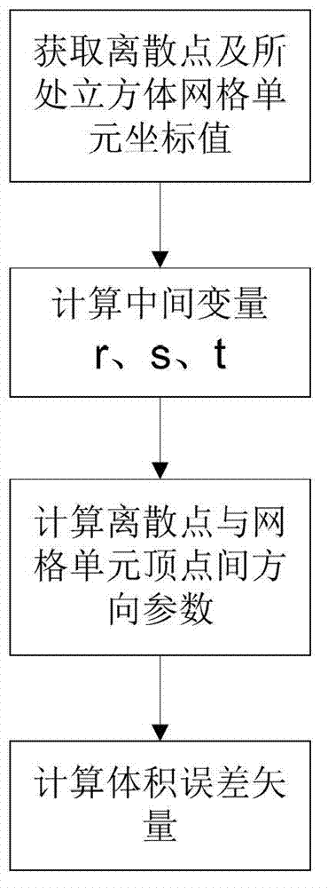
[0050] The main purpose of the invention is to effectively correct the grinding path of the numerical control grinding wheel by establishing an improved error estimation model based on kinematics transformation. Through the improved error model, the initial grinding wheel processing path can be input and the corrected grinding wheel processing path can be output. The overall process can be processed automatically, and the overall CNC grinding process can be completed efficiently and time-saving. Moreover, the improved error model or correction method can effectively reduce the deviation between the...


PUM


Abstract

The invention discloses a kinematic transformation based grinding machining method for a numerically controlled grinding wheel, which comprises the following steps of: generating an initial grinding wheel machining path and performing discretization treatment to produce a plurality of discrete points; selecting position points within the range of movement of a driving shaft of a grinding wheel rack, and meshing to produce a plurality of cube mesh units based on the position points; finding the cube mesh units respectively comprising the discrete points, and then calculating the volume error vectors of the discrete points in the mesh units; utilizing the volume error vectors to convert each discrete point, and then producing a plurality of new discrete points; and producing a new grinding wheel machining path by a fitting method and performing the corresponding grinding treatment. The invention also discloses an improvement on calculation of volume error vectors and a point compression processing mode. Through the method, the deviation between the actual grinding trajectory and the ideal grinding trajectory caused by the kinematic properties and geometry error of the numerically controlled grinder can be reduced, and the geometric accuracy and dimensional accuracy of machining can be correspondingly improved.

Description

technical field [0001] The invention belongs to the field of mechanical processing, and more specifically relates to a numerical control grinding wheel grinding method based on kinematics transformation. Background technique [0002] In the CNC grinding wheel grinding process, common processing methods include mechanical imitation shape grinding, full CNC grinding without templates, real-time interpolation technology, grinding wheel dressing and compensation, etc. However, for the CNC grinding method of the prior art, there are still the following defects: due to the kinematic characteristics and geometric errors of the CNC grinding machine itself, it is easy to cause a discrepancy between the actual trajectory of the grinding point and the ideal trajectory of the grinding wheel during the grinding process. Large deviation, and directly lead to the problem that the geometric accuracy and dimensional accuracy of the processed workpiece are reduced. [0003] In the patent lit...

Claims


Application Information

Patent Timeline
Patent Type & Authority Applications(China)
IPC IPC(8): B24B51/00
Inventor 黄禹邵新宇李明震张国军彭碧张尚柳懿麟
Owner HUAZHONG UNIV OF SCI & TECH
Why Eureka
Try Eureka