Combined guard board for preparing pseudo-single crystal with high utilization rate and method for preparing pseudo-single crystal

A technology of quasi-single crystal and utilization rate, which is applied in the direction of single crystal growth, single crystal growth, chemical instruments and methods, etc., can solve the problems affecting the utilization rate of ingot and low yield rate of ingot, and achieve good industrial prospects and low cost. Inexpensive, simple design effect

Inactive Publication Date: 2012-11-21
TIANWEI NEW ENERGY HLDG
View PDF3 Cites 2 Cited by
  • Summary
  • Abstract
  • Description
  • Claims
  • Application Information

AI Technical Summary

Problems solved by technology

[0005] Disadvantages of the existing technology: the casting quasi-single crystal technology first places the seed crystal and silicon material doping elements in the crucible, and the seed crystal is generally located at the bottom of the crucible
Although casting quasi-single crystal technology has been industrialized, there are still problems, that is, the yield rate of the ingot is currently low, only the current yield rate is about 40% to 60%, mainly due to the polycrystalline crystals around the ingot. The production of the ingot has seriously affected the utilization rate of the ingot

Method used


Image

  • Combined guard board for preparing pseudo-single crystal with high utilization rate and method for preparing pseudo-single crystal
  • Combined guard board for preparing pseudo-single crystal with high utilization rate and method for preparing pseudo-single crystal
  • Combined guard board for preparing pseudo-single crystal with high utilization rate and method for preparing pseudo-single crystal

Examples


Embodiment 1

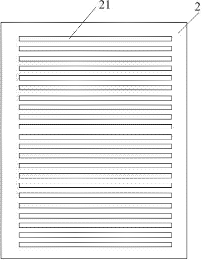
[0032] Such as Figure 1-6 Shown.

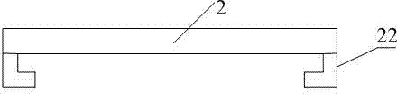
[0033] The key technical point to be protected by the present invention is the combined protective plate involved in the present invention. Among the more important aspects of the new combined protective plate involved in the present invention are: 1. The combined protective plate can be made of the same material, It can also be made of two different materials. 2. The combined protective plate is divided into two parts: inside and outside, which can move relative to each other, so that the protective plate is in an open and closed state. 3. There are through holes on the inner and outer guard plates. Under the premise of meeting the strength of the guard plate, the area of ​​the through holes on the inner and outer guard plates can be adjusted.

[0034] Therefore, a high-utility quasi-single crystal combined guard plate is prepared, including the crucible graphite side guard plate 3 attached to the outer wall of the crucible 4, and the crucible...


PUM


Abstract

The invention discloses a combined guard board for preparing a pseudo-single crystal with high utilization rate and a method for preparing the pseudo-single crystal, wherein the guard board is improved to realize different heat radiation intensities in different areas of a crucible, so as to improve a growth condition of the single crystal. The combined guard board for preparing the pseudo-single crystal with high utilization rate comprises a lateral crucible graphite guard board which is attached onto the outer wall of the crucible; the lateral crucible graphite guard board comprises an inner guard board attached onto the outer wall of the crucible, and an outer guard board attached onto one side of the inner guard board; the outer guard board is located on one side of the inner guard board far away from the crucible; a plurality of strip-shaped inner guard board holes with the axes being in parallel with one another are formed on the inner guard board; a plurality of strip-shaped outer guard board holes with the axes being in parallel with one another are formed on the outer guard board; and the axes of the strip-shaped inner guard board holes are in parallel with the axes of the strip-shaped outer guard board holes. With the adoption of the combined guard board, the ratio of the radial transmission to the vertical transmission of the heat from the crucible is greatly decreased so as to effectively inhibit the radial heat current of the crucible, and the formation proportion of polycrystal around a cast ingot is decreased, so that the utilization rate of the cast ingot is increased.

Description

Technical field [0001] The invention relates to equipment for preparing single crystal silicon, in particular to a combined guard plate for preparing quasi-single crystals with high utilization rate and a method for preparing quasi-single crystals. Background technique [0002] At present, crystalline silicon solar cells have always occupied the solar cell market due to their high efficiency and stability. Due to the large number of grain boundaries and dislocations in cast polysilicon, they can introduce deep energy levels in the silicon forbidden band and become an effective recombination center for light-generated minority carriers. At the same time, cast polysilicon cannot be used because of the different crystal orientations of the crystal grains. The anisotropic alkali texturing method performs surface treatment, and the isotropic acid texturing method is difficult to achieve the same effect, making the conversion efficiency of polycrystalline silicon solar cells about 1.5 ...

Claims


Application Information

Patent Timeline
Patent Type & Authority Applications(China)
IPC IPC(8): C30B11/00C30B29/06
Inventor 罗大伟林洪峰张凤鸣王临水路忠林
Owner TIANWEI NEW ENERGY HLDG
Why Eureka
Try Eureka