Heat pump air-conditioning system of electric vehicle

A heat pump air conditioner and electric vehicle technology, applied in air conditioning systems, home heating, heating methods, etc., can solve the problems of heat absorbed by the heat exchanger outside the car, the system cannot continue to provide heating functions, and the system cannot continue to operate, etc., to achieve improvement Operating environment, the effect of increasing temperature

Inactive Publication Date: 2012-11-21
TIANJIN SANDEN AUTO AIR CONDITIONING
View PDF4 Cites 44 Cited by
  • Summary
  • Abstract
  • Description
  • Claims
  • Application Information

AI Technical Summary

Problems solved by technology

This system is in Figure 5 Improvements are made on the basis of the system shown, adding an in-car condenser 2, an expansion valve 17, two check valves (18, 19), and two shut-off valves (5, 6). It can realize the function of heating and dehumidification, but because in the heating cycle, the external heat exchanger is used as an evaporator and needs to absorb the heat of the external environment, so when the external temperature is low, the temperature of the external heat exchanger is close to the external ambient temperature , the ex

Method used


Image

  • Heat pump air-conditioning system of electric vehicle
  • Heat pump air-conditioning system of electric vehicle
  • Heat pump air-conditioning system of electric vehicle

Examples


Embodiment approach 1

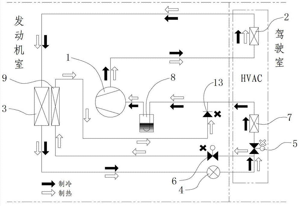
[0026] see figure 1 , electric vehicle heat pump air conditioning system, including compressor 1, interior condenser 2, exterior condenser 3, expansion valve 4, first stop valve 5, second stop valve 6, interior evaporator 7 and liquid-gas separator 8. It also includes an exterior evaporator 9, which is arranged behind the exterior condenser. According to the flow direction of the refrigerant, the outlet of the compressor and the inlet of the condenser outside the vehicle are connected through pipelines to form a first stroke section, and the condenser inside the vehicle is connected in series on the stroke section. A second travel section is formed between the inlet and the outlet of the exterior condenser. A third stroke section is formed between the outlet of the exterior condenser and the inlet of the liquid-gas separator, and this stroke section includes the first branch circuit and the second branch circuit formed by the first shut-off valve and the interior evaporator ...

Embodiment approach 2

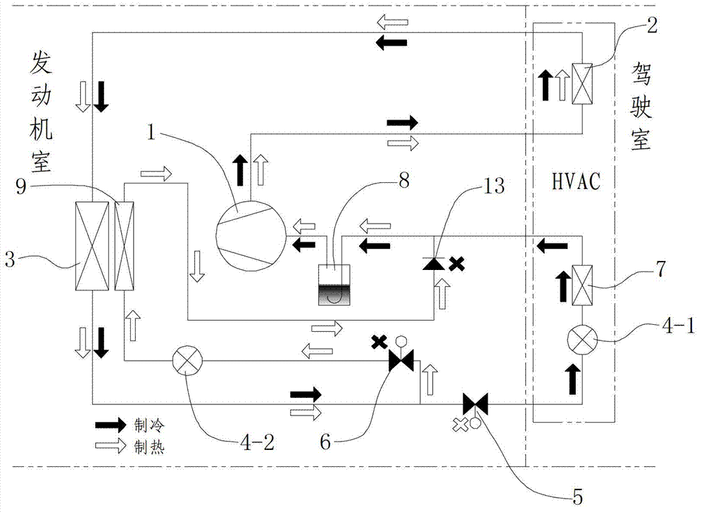
[0031] see figure 2 , the difference between this embodiment and Embodiment 1 is that there are two expansion valves, and the inlet of one expansion valve (referred to as the first expansion valve 4-1 here) is connected to the outlet of the first cut-off valve. The outlet of the valve is connected with the inlet of the evaporator inside the vehicle; the inlet of another expansion valve (called the second expansion valve 4-2 here) is connected with the outlet of the second cut-off valve, and the outlet of the expansion valve is connected with the outlet of the evaporator outside the vehicle. The import is connected.

[0032] For the working principle of this embodiment, please refer to Embodiment 1. The difference from Embodiment 1 is that in Embodiment 1, an expansion valve is used to control the first branch and the second branch. An expansion valve, independently controlled.

Embodiment approach 3

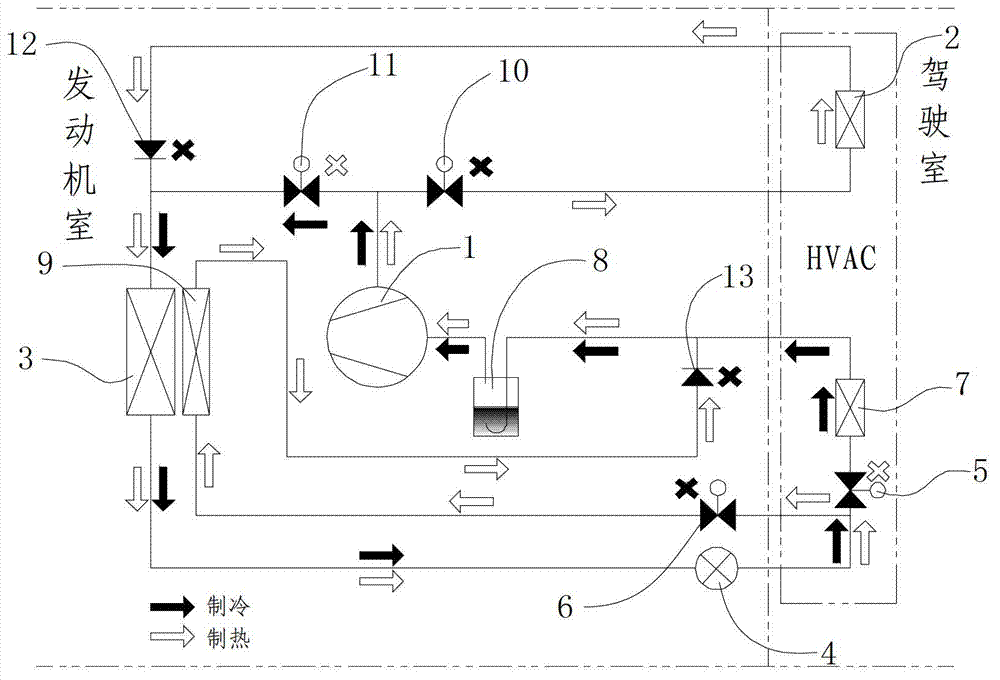
[0034] see image 3 , The difference between this embodiment and Embodiment 1 is that: the third stop valve 10 and the fourth stop valve 11 are installed on the first stroke section. The outlet of the compressor is respectively connected with the inlet of the third shut-off valve and the inlet of the fourth shut-off valve through a three-way joint. According to the flow direction of the refrigerant, the third cut-off valve is connected in series with the interior condenser to form a third branch, and the fourth branch is formed between the inlet and outlet of the fourth cut-off valve, and the third branch and The fourth branch is connected in parallel.

[0035] How this implementation works:

[0036]During the heating cycle, the third cut-off valve is opened and the fourth cut-off valve is closed. The refrigerant is compressed by the compressor and becomes a high-temperature and high-pressure gaseous refrigerant. During the heat release process, the surrounding air is heate...


PUM


Abstract

The invention relates to a heat pump air-conditioning system of an electric vehicle. The heat pump air-conditioning system comprises a compressor, a condenser inside the vehicle, a condenser outside the vehicle, expansion valves, a first stop valve, a second stop valve, an evaporator inside the vehicle and a liquid and gas separator. The heat pump air-conditioning system is characterized by further comprising an evaporator outside the vehicle. A first stroke section is formed between an outlet of the compressor and an inlet of the condenser outside the vehicle, and the condenser inside the vehicle is serially connected onto the stroke section; a second stroke section is formed between an inlet and an outlet of the condenser outside the vehicle; a third stroke section is formed between an outlet of the condenser outside the vehicle and an inlet of the liquid and gas separator and comprises a first branch and a second branch, the first stop valve and the evaporator inside the vehicle are serially connected to form the first branch, the second stop valve and the evaporator outside the vehicle are serially connected to form the second branch, and the expansion valves are arranged at front ends of the two evaporators; and a fourth stroke section is formed between the inlet and an outlet of the liquid and gas separator. The evaporator outside the vehicle is arranged behind the condenser outside the vehicle, heat discharged from the condenser outside the vehicle is transferred to the evaporator outside the vehicle, so that the temperature of the periphery of the evaporator outside the vehicle is increased, and working conditions at the temperature below minus 5 DEG C are met.

Description

technical field [0001] The invention relates to an automobile air-conditioning system, in particular to an electric automobile heat pump air-conditioning system. Background technique [0002] Electric vehicles do not have the engine waste heat that traditional vehicles use for heating, so they cannot provide a heating source. Therefore, the air-conditioning system of electric vehicles must have its own heating function, that is, heat pump air-conditioning system and / or electric heating are used for heating. At present, there are two common heat pump systems as follows, see Figure 5 and Figure 6 : [0003] Figure 5 It is the simplest and common heat pump system for automobile air conditioners. The heat pump system is composed of a compressor 1, a four-way reversing valve 14, an external heat exchanger 15, an internal heat exchanger 16, a liquid-gas separator 8 and an expansion valve 4. . The heat pump system uses few parts and low cost, and the flow direction of the re...

Claims


Application Information

Patent Timeline
IPC IPC(8): F24F5/00F24F13/30F25B41/04F25B41/06
CPCY02B30/72Y02B30/70
Inventor 仝增润
Owner TIANJIN SANDEN AUTO AIR CONDITIONING
Why Eureka
Try Eureka