Three-dimensional (3D) liquid crystal display driving method and 3D liquid crystal display system

A technology of liquid crystal display and driving method, which is applied in the direction of static indicators, optics, instruments, etc., can solve the problems of small crosstalk, large crosstalk ghosting, high product cost, etc., and achieve the effect of shortening the scanning time of liquid crystal and lowering the specification requirements

Active Publication Date: 2012-11-21
HISENSE VISUAL TECH CO LTD
View PDF4 Cites 16 Cited by
  • Summary
  • Abstract
  • Description
  • Claims
  • Application Information

AI Technical Summary

Problems solved by technology

[0005] However, the current light guide plate and backlight technology cannot realize that only the area corresponding to the light bar is turned on, and the area where the light bar is not turned on is not bright, so the crosstalk rate of the left and right eyes is relatively large during this kind of 3D display, and at the same time, it corresponds to the area of ​​the LCD. Response speed requirements are strict, resulting in high product cost, 3D effect and large crosstalk ghosting of the left and right eyes (the left eye sees the image of the right eye)
[0006] Recently, 240Hz 3D display technology with better display effect has emerged, and its backlight generally adopts a blinking method (such as Figure 5 As shown) and the backlight is always on. This display technology requires the liquid crystal to respond very quickly. At present, only a few manufacturers have mastered the copper process to reduce the charging time of the liquid crystal and the 240Hz full scan technology, and it exists in the display screen. The trade-off between upper, middle and lower brightness unevenness and small crosstalk, in addition, it also requires LCD panels with high specifications (short charging time), chips with fast operation speed (high IC specifications), and a new high-speed signal interface (AIPI)

Method used


Image

  • Three-dimensional (3D) liquid crystal display driving method and 3D liquid crystal display system
  • Three-dimensional (3D) liquid crystal display driving method and 3D liquid crystal display system
  • Three-dimensional (3D) liquid crystal display driving method and 3D liquid crystal display system

Examples


Embodiment 1

[0037] like Image 6 As shown, this embodiment records a 3D liquid crystal display driving method, comprising the following steps:

[0038] S1: In 3D display mode, at least two scan clock signals are generated within one data signal output period of the effective data area of ​​the left and right eyes; the input image signal is processed to form left and right eyes corresponding to the scan clock signals a valid data area signal; the left and right eye valid data area signals correspond to the left and right eye valid data areas;

[0039] S2: Synchronously output the at least two scan clock signals;

[0040] S3: Drive the liquid crystal panel to scan at least two lines synchronously according to the at least two scanning clock signals, and display the processed image signal.

[0041] This embodiment greatly reduces the liquid crystal scanning time, greatly reduces the specification requirements for the liquid crystal panel and chip of the 3D display with a high refresh rate ...

Embodiment 2

[0043] In this embodiment, before the step S1 in the first embodiment, a step of judging the 2D / 3D control signal is also included:

[0044] If the 2D / 3D control signal is in the 2D display mode, a scan clock signal is generated within one data output cycle to drive the liquid crystal panel to perform progressive scan;

[0045] If the 2D / 3D control signal is a 3D display mode, go to step S1.

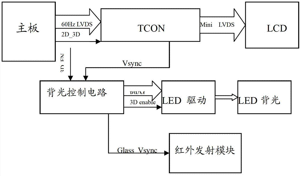
[0046] Through the method of this embodiment, in addition to the high 3D display effect achieved by the ordinary liquid crystal panel, chip and backlight system described in the first embodiment, the 2D and 3D conversion display of the liquid crystal display system can also be realized, so that the liquid crystal display system At the same time, the 60Hz or 120Hz progressive scanning method is realized in the 2D display mode, so that the image resolution does not change.

Embodiment 3

[0048] This embodiment includes the content of Embodiment 1 or Embodiment 2, and more specifically: in this embodiment, in the step S1, two Scanning clock signals: In the step S2, the two scan clock signals are output synchronously by covering the front and rear edges of the output enable signal in the data signal output cycle with the front and rear edges of one scan clock signal. In other embodiments of the present invention, three or more scan clock signals can be generated within one data signal output period, and at this time, the input image signal needs to be processed correspondingly into higher frequency left and right eye Valid data area signal.


PUM


Abstract

The invention discloses a three-dimensional (3D) liquid crystal display driving method which includes the following steps: S1, generating at least two scanning clock signals in a data signal output period, outputting corresponding effective data area signals of a left eye and a right eye after processing input image signals; S2, outputting at least two scanning clock signals synchronously; and S3, driving the liquid crystal panel to conduct at least two lines of scanning synchronously and displaying the processed image signals according to the at least two scanning clock signals. The invention further discloses a display system which comprises a time schedule controller and a grid driver. The time schedule controller comprises a STV, CKV and OE processing circuit which is used for processing the input image signals. The grid driver is used for driving the liquid crystal panel to conduct at least two lines of scanning synchronously. The 3D liquid crystal display driving method and the 3D liquid crystal display system reduce liquid crystal scanning time and lower requirements of 3D display refreshed at high speed for the liquid crystal panel and a chip.

Description

technical field [0001] The invention relates to the technical field of liquid crystal display, in particular to a 3D liquid crystal display driving method and a 3D liquid crystal display system. Background technique [0002] like figure 1 As shown, the traditional 120Hz driving 3D technology without backlight scanning opens the glasses to watch the 3D effect in the blank (Blank) area after the image scanning is completed, but this has the problem that the flipping time of the upper and lower liquid crystals of the LCD panel is inconsistent and the viewing time is short. [0003] Different from the above-mentioned traditional 120Hz 3D SG control method without backlight scanning, there is also a 120Hz 3D display method using backlight scanning in the prior art. Its circuit control block diagram is as follows figure 2 Shown: The motherboard gives 60Hz signal LVDS (low voltage differential signal) (left, right, up and down, row interleaving, etc.), and the timing controller ...

Claims


Application Information

Patent Timeline
Patent Type & Authority Applications(China)
IPC IPC(8): G09G3/36G02F1/133G02B27/22
Inventor 黄顺明徐爱臣曹建伟刘卫东
Owner HISENSE VISUAL TECH CO LTD
Why Eureka
Try Eureka