
Broadband wireless data card antenna

A wireless data card, broadband wireless technology, applied in the direction of antenna, antenna grounding device, antenna support/installation device, etc., can solve the problems of affecting antenna transmission characteristics and communication performance, high cost, etc., to reduce electric field power and reduce SAR value , reducing the effect of centralized distribution

Inactive Publication Date: 2012-11-21
UNIV OF ELECTRONICS SCI & TECH OF CHINA
View PDF3 Cites 6 Cited by
  • Summary
  • Abstract
  • Description
  • Claims
  • Application Information

AI Technical Summary

Problems solved by technology

In the existing low-SAR antenna technical solutions, new high-permeability materials are often used to make antennas to maximize the proportion of magnetic field energy in the near-field of the data card antenna and reduce the proportion of electric field energy in the near-field, so as to achieve low-power antennas. The purpose of the SAR value, however, due to the complexity of the antenna structure of the wireless data card and the variability of the use environment, the above scheme often fails and the cost is high
There are also some antennas that are designed simply by reducing the radiation power to achieve the purpose of controlling the SAR value, which will significantly affect the transmission characteristics and communication performance of the antenna

Method used


Image

  • Broadband wireless data card antenna
  • Broadband wireless data card antenna
  • Broadband wireless data card antenna

Examples


Embodiment 1

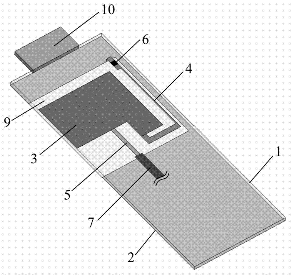
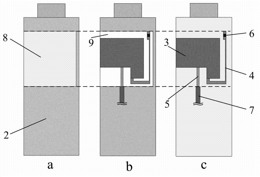
[0026] Such as figure 1 As shown, the wireless data card includes a data card main board 1 and a USB interface 10 . The USB interface 10 is used for the connection between the wireless data card and the wireless device. Such as figure 2 As shown in a and 2c, the antenna radiation system on the main board 1 of the data card is distributed on two surfaces (upper layer and lower layer) of the main board 1 of the data card. The antenna wiring is set on the upper layer of the main board 1 of the data card. The wires include patches 3, narrow strips 4 and connection strips 5 that are connected together. The metal ground 2 is set on the lower layer of the data card main board 1. The settings of the two sides are as follows: figure 2 shown. Such as figure 2 As shown in c, the narrow strip 4 on the upper layer is also loaded with a lumped capacitor 6, and the connecting strip 5 is connected to a 50-ohm microstrip feeder 7. Such as figure 2 As shown in b, the metal-free area 8...

Embodiment 2

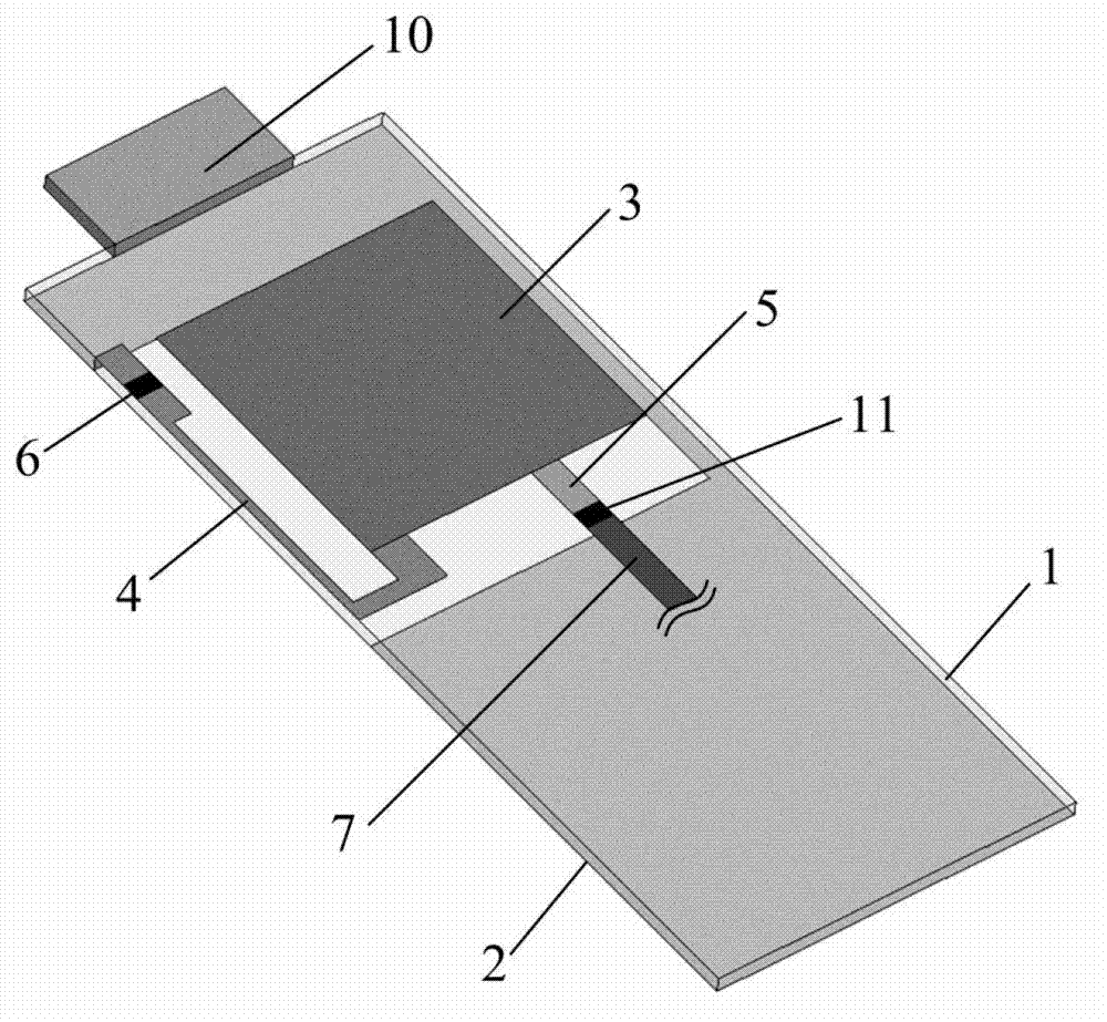
[0036] It is another antenna form with the same principle as that of Embodiment 1.

[0037] Such as image 3 As shown, the wireless data card includes a data card main board 1 and a USB interface 10 . The USB interface 10 is used for the connection between the wireless data card and the wireless device. Such as Figure 4 As shown in a and 4c, the antenna radiation system on the main board 1 of the data card is distributed on two surfaces (the upper layer and the lower layer) of the main board 1 of the data card. The antenna wiring is set on the upper layer of the main board 1 of the data card. The wires include patches 3, narrow strips 4 and connection strips 5 that are connected together. The metal ground 2 is set on the lower layer of the data card main board 1. The settings of the two sides are as follows: Figure 4 shown. Such as Figure 4 As shown in c, the narrow strip 4 on the upper layer is also loaded with a lumped capacitor 6, and the connecting strip 5 is conne...


PUM


Abstract

The invention relates to a broadband wireless data card antenna, which is characterized in that antenna cabling and a metal floor collectively form an antenna radiation system, the antenna cabling is directly printed or welded on one surface of a wireless data card main board, and the metal floor is printed on the other surface of the wireless data card main board. The metal corresponding to the orthographic projection area of the antenna cabling on the metal floor is completely hollowed, so that a semi-closed metal-free area is formed on the metal floor, and since a patch of the antenna cabling and the metal floor are respectively arranged on two surfaces of the wireless data card main board, a coupling clearance is conveniently formed between the patch and the metal floor. The clearance coupling between the antenna cabling and the metal floor can play a role of distributive capacitance; and meanwhile, a narrow band in the antenna cabling can play a role of distributive inductance, and the input impedance of the antenna can be effectively adjusted, so that the antenna produces resonance within a needed frequency band to form a wider bandwidth.

Description

technical field [0001] The invention belongs to an antenna in the technical field of wireless mobile equipment, and in particular relates to data card antenna technology. Background technique [0002] With the continuous development of the global 3G communication network, wireless communication and data transmission have become an important way for people to use new technologies. As a way of wireless Internet access, wireless data cards with antennas have the advantages of fast transmission speed, convenient use, and being online anytime and anywhere. Therefore, in the future market, it is an inevitable trend for wireless devices to be equipped with wireless data cards. As an important part of the wireless data card, the antenna directly affects the transmitting and receiving performance of the wireless device. At present, the challenge of realizing the wireless data card antenna is to realize the multi-band / broadband antenna with low SAR (Specific Absorption Rate, Specific...

Claims


Application Information

Patent Timeline
Patent Type & Authority Applications(China)
IPC IPC(8): H01Q1/38H01Q1/48H01Q1/22H01Q13/08
Inventor 班永灵孙思成刘成丽
Owner UNIV OF ELECTRONICS SCI & TECH OF CHINA
Learn More