
Valve assembly

A technology of valves and valve stems, which is applied in the direction of valve devices, lift valves, engine components, etc., which can solve the problems of weakening valves, hindering exhaust gas discharge and entry, and achieve the effect of simplifying the structure

Active Publication Date: 2015-04-01
MAN DIESEL & TURBO FILIAL AF MAN DIESEL & TURBO SE TYSKLAND
View PDF7 Cites 0 Cited by
  • Summary
  • Abstract
  • Description
  • Claims
  • Application Information

AI Technical Summary

Problems solved by technology

Holes on the top side necessarily lead to a considerable weakening of the valve, which has to be compensated by other reinforcements, which increases the construction effort
In addition, with this known device there is the danger that blown air in the region of the valve seat can enter the working chamber when the valve is open or prevent the exhaust gas from being evacuated.

Method used


Image

  • Valve assembly
  • Valve assembly

Examples


Embodiment Construction

[0024] The main field of application of the invention is the exhaust valve arrangement of large two-stroke engines, especially large two-stroke diesel engines, as they are used for marine drives and the like. Engines of this type generally have an air intake for fresh gas arranged in the lower area of ​​each cylinder and a respective centrally arranged exhaust gas outlet in the cylinder head of each cylinder, to which a valve is assigned . The exhaust valves arranged in the region of the upper cylinder are here subjected to a particularly high thermal load, so that cooling is expedient.

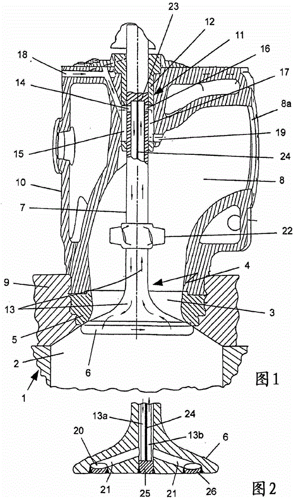
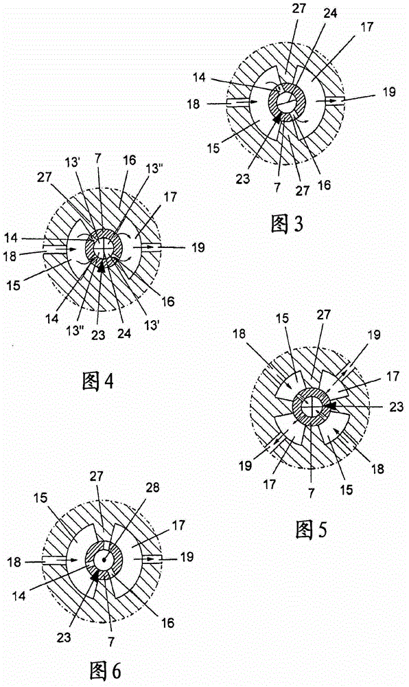
[0025] exist figure 1The cylinder 1 shown in the figure delimits a working chamber 2, which can be supplied with scavenging gas in its lower region, not shown, via an inlet controllable by a piston, also not shown, and whose upper boundary contains an exhaust gas outlet 3. Assigned to the exhaust gas outlet is an exhaust valve, hereinafter referred to as valve 4, which is designed as a pop...


PUM


Abstract

The invention relates to a valve assembly, comprising a valve (4) which is associated with a gas conduit (8), has a valve disc (6) and a valve stem (7) supporting said valve disc and is provided with a cooling device. In said valve assembly, a simple design, high functional reliability and a good energy balance can be achieved by using a gaseous cooling medium or a cooling medium which consists at least partially of components that can be converted into a gaseous state. The cooling medium is discharged as gas into a gas conduit (8) via at least one outlet chamber (17), and for this purpose each discharge duct (19) originating from the outlet chamber (17) opens into a gas conduit (8).

Description

technical field [0001] The invention relates to a valve device, comprising a valve provided for a gas channel of an engine, especially a large two-stroke diesel engine, having a valve crown and a valve stem supporting the valve crown, provided with a cooling device, wherein the cooling The device has at least one flow path extending in the valve to which a cooling medium can be applied, which flow path communicates with at least one supply chamber delimited by the valve stem to which the cooling medium can be supplied and with at least one discharge chamber delimited by the valve stem In communication, at least one exhaust pipe is passed out from the exhaust chamber. Further subjects relate to a valve housing, a valve and a guide bush for a valve arrangement of the above-mentioned type, as well as an engine with a valve arrangement of the above-mentioned type. Background technique [0002] A device of the aforementioned type is known, for example, from DK 173 452 B1. In th...

Claims


Application Information

Patent Timeline
Patent Type & Authority Patents(China)
IPC IPC(8): F01L3/12F01L3/16F01L3/18
CPCF01L3/12F01L3/18F01L3/16
Inventor A·K·彼德森H·H·约根森
Owner MAN DIESEL & TURBO FILIAL AF MAN DIESEL & TURBO SE TYSKLAND
Learn More