Block type multidirectional forging device

A multi-directional forging and blocking technology, applied in forging/pressing/hammer devices, forging presses, forging presses, etc., can solve problems such as frame or base deformation, low work efficiency, and workpiece processing errors

Active Publication Date: 2013-07-24
江西国瑞重工有限公司
View PDF7 Cites 0 Cited by
  • Summary
  • Abstract
  • Description
  • Claims
  • Application Information

AI Technical Summary

Problems solved by technology

[0005] In order to solve the problems that the existing forging device often deforms the frame or the base during the process of extruding the workpiece, which leads to the processing error of the workpiece, affects the forging accuracy, high production cost, and low work efficiency. A closed-type multi-directional forging device is developed to effectively ensure the forging accuracy, reduce or avoid the occurrence of defective products, improve work efficiency, and reduce production costs.

Method used


Image

  • Block type multidirectional forging device
  • Block type multidirectional forging device
  • Block type multidirectional forging device

Examples


Embodiment 1

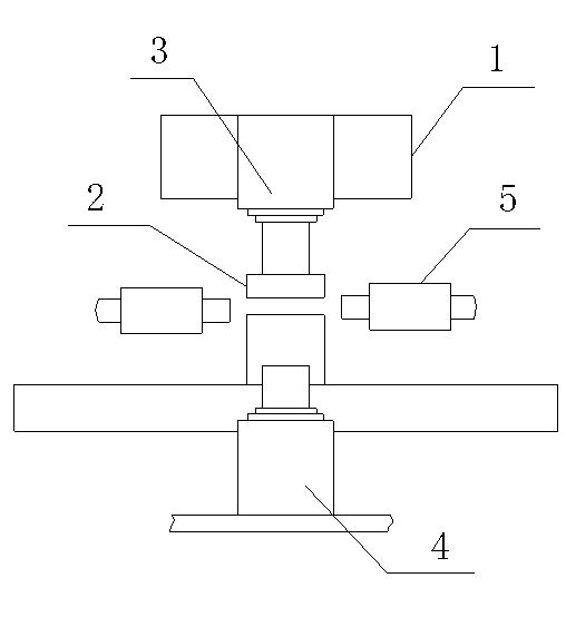
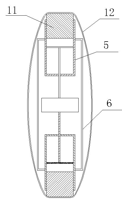
[0025] like figure 1 , 2 As shown, a closed-type multi-directional forging device includes a frame 1, a mold 2 for forming products, and a hydraulic transmission device fixedly arranged on the frame 1 and acting on the mold 2; the hydraulic transmission device includes a The main cylinder 3 above the mold 2, the jacking cylinder 4 arranged under the mold 2 for blanking, and the lateral extrusion cylinder 5 for laterally extruding the workpiece, there are two lateral extrusion cylinders 5, The rear end of the lateral extruding cylinder 5 is provided with movable elements that can move along the inner wall of the lateral extruding cylinder 5; The outside is a fastener that fixedly connects multiple movable elements in turn, and the fastener is a closed ring structure.

[0026] By setting movable elements at the rear end of the lateral extrusion cylinders and making the movable elements fixedly connected with the fasteners, when each lateral extrusion cylinder is extruding the ...

Embodiment 2

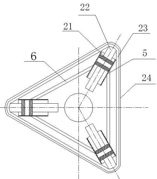
[0030] like image 3 As shown, the rest are the same as in Embodiment 1, the difference is that the lateral extruding cylinders 5 are 3 evenly distributed, and the movable element is the lower piston 21 arranged on the inner side of the lateral extruding cylinders 5, and the lower piston 21 is provided with Connecting rod 22 is arranged, and connecting rod 22 stretches out and fixes with fastener on the outside of lateral extruding oil cylinder 5. The fastener is a polygonal frame 23, or a wound steel belt 24 or a steel wire rope, or a polygonal frame 23 with a steel belt 24 or a steel wire rope wound outside. The frame 23 is a triangular frame, and the fasteners are inscribed to the movable elements. When the lateral extrusion oil cylinder 5 does work, the reaction force produced will push the lower piston 21 and the connecting rod 22 to move. The force produced by each lateral extrusion cylinder is balanced, and the force does not act on the frame, which reduces the load-b...


PUM


Abstract

The invention discloses a block type multidirectional forging device, which comprises a frame, a die for forming a product and a hydraulic transmission device. The hydraulic transmission device comprises a main cylinder, a jacking cylinder and at least two lateral extrusion cylinders, wherein a movable element is arranged at the rear end of each lateral extrusion cylinder; and the frame comprisesa bracket and fasteners in wrapped connection with the outer sides of the movable elements and used for fixedly connecting a plurality of movable elements sequentially, and each fastener has a closedannular structure. According to the device, the movable elements are arranged at the rear ends of the lateral extrusion cylinders and fixedly connected with the fasteners, and when each lateral extrusion cylinder extrudes a workpiece, a force reacting on the frame can directly act on the fasteners; and because the fasteners have the closed annular structures, stress balance at each position of the fasteners is ensured, the forging precision is effectively ensured, degraded products are reduced or avoided, the working efficiency is improved, and the production cost is reduced.

Description

technical field [0001] The invention relates to a forging device, in particular to a closed multi-directional forging device. Background technique [0002] Due to its high power and good working stability, hydraulic cylinders are often used as power components in the field of machining, especially in the forging industry. [0003] In the process of forging and forming the workpiece with the closed multi-directional forging device, through the action of the hydraulic system, the main oil cylinder moves down to block and lock the upper and lower molds, and the side extrusion cylinder performs side extrusion inward. After the workpiece is formed, the side Return to the extrusion cylinder, the main cylinder returns, and the ejector cylinder ejects and returns the formed product to complete the forming process of the product. In the existing forging device, the lateral extrusion cylinder is generally fixedly arranged on the frame or the base. During the process of extruding the ...

Claims


Application Information

Patent Timeline
Patent Type & Authority Patents(China)
IPC IPC(8): B21J9/02B21J13/04
Inventor 黄建辉
Owner 江西国瑞重工有限公司
Why Eureka
Try Eureka